
Intelligent laser obstacle clearing instrument

A technology of obstacle removal instrument and laser, which is applied in the field of obstacle removal instrument, can solve problems such as laser removal of tree obstacles, endangering the safety of power grid operation, secondary personal injury, etc., and achieves compact and precise transmission structure, high electro-optical conversion efficiency, and low power consumption. low effect

Pending Publication Date: 2019-11-08
NANTONG SIPAITE LASER TECH
View PDF0 Cites 7 Cited by
  • Summary
  • Abstract
  • Description
  • Claims
  • Application Information

AI Technical Summary

Problems solved by technology

[0002] The power grid is mainly erected in the air by bare metal wires through poles and towers to remove the interference of hanging objects. Power lines in some areas are still facing the contradiction of "line tree conflict"; whether it is low-voltage distribution lines or high-voltage transmission lines, they will be affected by super tall trees High-voltage overhead lines are mostly outside urban areas, and many of the trees encountered are fast-growing trees. Excessive growth speed can easily make the trees super tall, which in turn affects the safe operation of the line, and may cause single-phase grounding , arc short circuit, disconnection and other faults, causing tripping, damage to distribution lines caused by trees, and may also cause secondary injuries to people, and broken wires may cause fires and electric shocks; traditional operators need to use only Speeding or manual climbing to clear the tree barriers, some trees growing on the cliffs make cleaning more difficult, and the safety of the operation cannot be guaranteed; laser obstacle clearing uses laser beams to irradiate the tree barriers to burn and cut the tree barriers, thereby removing Removal of tree barriers enables remote clearing of obstacles, simplifies the process of clearing obstacles, and improves the safety of staff; however, the existing laser obstacle removal methods cannot maximize the use of lasers to remove tree obstacles, and it takes too long to clear them quickly

Method used


Image

  • Intelligent laser obstacle clearing instrument
  • Intelligent laser obstacle clearing instrument
  • Intelligent laser obstacle clearing instrument

Examples


Embodiment Construction

[0027] In order to make the technical means, creative features, goals and effects achieved by the present invention easy to understand, the present invention will be further described below in conjunction with specific embodiments.

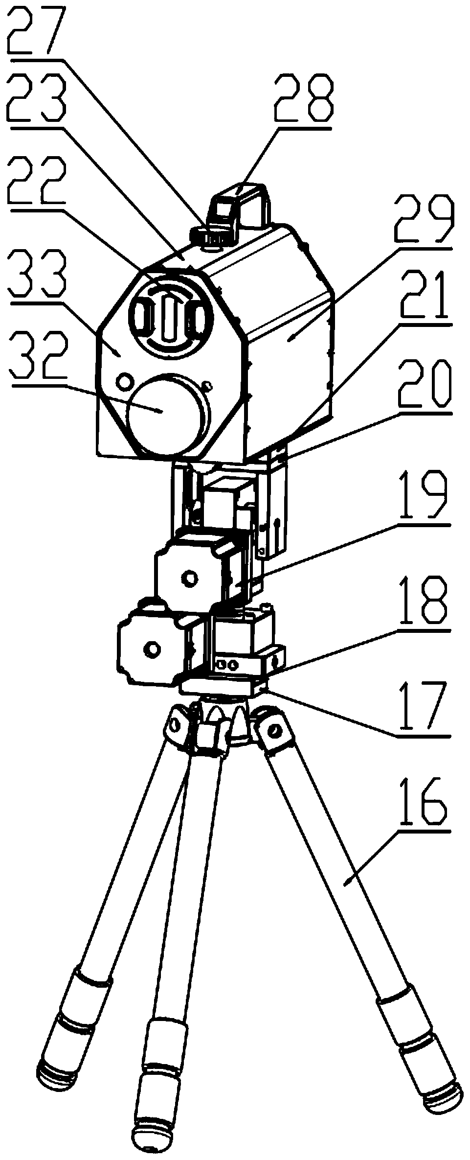
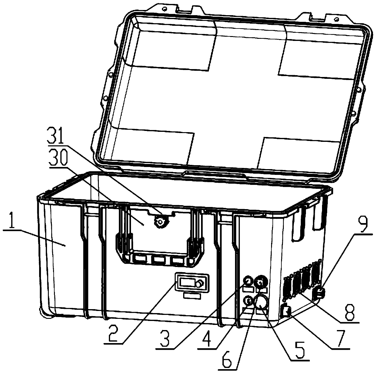
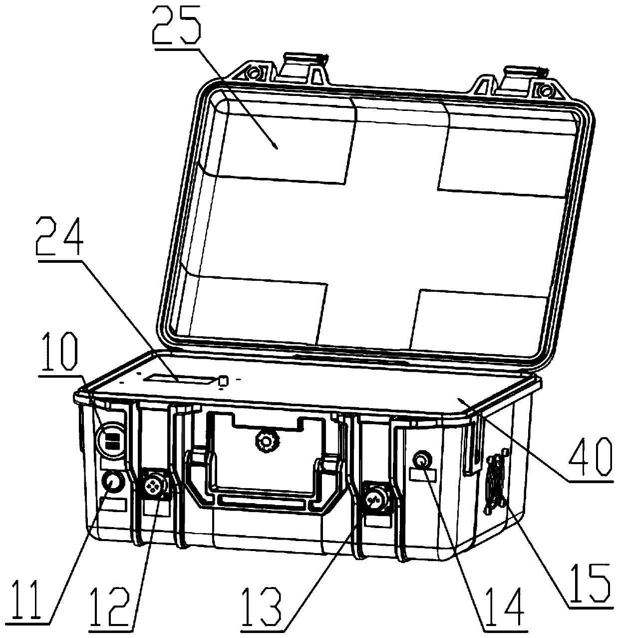
[0028] Such as Figure 1-Figure 5 As shown, an intelligent laser obstacle removal instrument according to the present invention includes a main laser box 1, a power adjustment device 2 is installed on the front side wall of the main laser box 1, and the main laser box 1 is installed above the power adjustment device 2. There is a fiber laser 30, the laser main box 1 is located above the fiber laser 30, and a GPRS remote control device 31 is installed. The laser main box 1 is located on the side of the power adjustment device 2 and is connected to a No. 1 indicator light 3, and the laser main box 1 is located at No. 1 indicator The end of the lamp 3 away from the power adjustment device 2 is connected with a laser safety alarm 6, the laser main box...


PUM


Abstract

The invention relates to the field of obstacle clearing instruments, in particular to an intelligent laser obstacle clearing instrument which comprises a laser mainframe box; a power adjusting deviceis mounted on the side wall of the front end of the laser mainframe box, and the intelligent laser obstacle clearing instrument has the advantages that the intelligent laser obstacle clearing instrument adopts an optical fiber laser, the electro-optical conversion efficiency is high, and the power consumption of the whole machine is low; laser output can be dynamically focused, laser power is utilized to the maximum extent, and obstacle removing operation is accurately conducted; an electric intelligent cradle head adopts a precise turbine worm speed reducer, so that the transmission structureis compact and precise; a GPRS remote control device is arranged, authorization permission and authority management can be carried out on the equipment through a mobile phone APP, and the position ofthe equipment can be monitored in real time, so that risk management and control can be effectively carried out on the equipment, and the use safety of the equipment is improved; a remote control keyboard integrating target display, direction control and laser control is adopted for aiming, cradle head direction adjustment, laser power adjustment and light emitting control.

Description

technical field [0001] The invention relates to the field of obstacle removal instruments, in particular to an intelligent laser obstacle removal instrument. Background technique [0002] The power grid is mainly erected in the air by bare metal wires through poles and towers to remove the interference of hanging objects. Power lines in some areas are still facing the contradiction of "line tree conflict"; whether it is low-voltage distribution lines or high-voltage transmission lines, they will be affected by super tall trees High-voltage overhead lines are mostly outside urban areas, and many of the trees encountered are fast-growing trees. Excessive growth speed can easily make the trees super tall, which in turn affects the safe operation of the line, and may cause single-phase grounding , arc short circuit, disconnection and other faults, causing tripping, damage to distribution lines caused by trees, and may also cause secondary injuries to people, and broken wires may...

Claims


Application Information

Patent Timeline
Patent Type & Authority Applications(China)
IPC IPC(8): H02G1/02B23K26/36B23K26/70H04N21/4363G08C17/02H04B10/50H04N7/18
CPCH02G1/02B23K26/36B23K26/702H04N21/43635G08C17/02H04B10/503H04N7/18
Inventor 桑魏魏袁建冯军军钱渠马锋成戴朝振钱海林
Owner NANTONG SIPAITE LASER TECH
Learn More