Composite hole evaporation heat exchange tube
A technology of composite holes and heat exchange tubes, which is applied in evaporator/condenser, lighting and heating equipment, refrigeration components, etc., can solve the problem of inconsistency in the size of the cavity structure, affecting the heat transfer performance of the evaporator tube, and the shape of T-shaped fins Irregularity and other problems, to achieve uniform pore structure, enhance boiling heat transfer, and increase the effect of vaporization core
- Summary
- Abstract
- Description
- Claims
- Application Information
AI Technical Summary
Problems solved by technology
Method used
Image
Examples
Embodiment 1
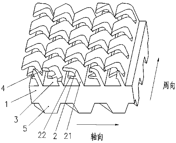
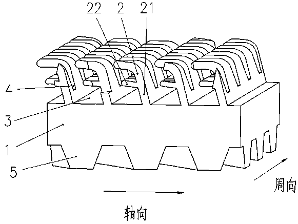
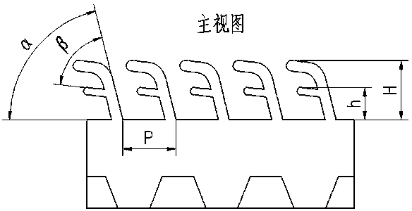
[0029] refer to figure 1 , figure 2 Shown is a schematic structural view of the first embodiment of a composite cavity evaporation heat exchange tube of the present invention. In this preferred embodiment, the heat exchange tube includes a tube body 1 with an inner cavity, and the outer surface of the tube body 1 is The outer fins 21 that are distributed in a spiral shape and are integrated with the tube body 1 are provided, and the secondary lateral fins 22 are arranged on one side of the outer fins 21, and the composite fins formed by this structure make the fins The single hole structure between them becomes a compound hole structure, which further increases the vaporization core when the refrigerant evaporates; image 3 As shown, the top of the outer fin 21 is formed into an inclined shape by blade processing, and the inclined direction is consistent with the extending direction of the secondary lateral fin 22 and is inclined to the left, thereby forming an F-shaped oute...
Embodiment 2
[0031] refer to Figure 5 , Figure 6 As shown, it shows a schematic structural view of the second embodiment of a compound hole evaporation heat exchange tube of the present invention. In this preferred embodiment, its basic structure and principle are the same as those of the first embodiment, except that: Figure 7 , Figure 8 As shown, the inclination direction of the fins 21 of the heat exchange tube is consistent with the extension direction of the secondary lateral fins 22 and is inclined to the right; the inclination angle α of the fins 21 is 89°; the secondary lateral fins The included angle β between the sheet 22 and the fin 21 is 89°.
PUM
 Abstract
Description
Claims
Application Information
 - R&D
- Intellectual Property
- Life Sciences
- Materials
- Tech Scout
- Unparalleled Data Quality
- Higher Quality Content
- 60% Fewer Hallucinations
Browse by: Latest US Patents, China's latest patents, Technical Efficacy Thesaurus, Application Domain, Technology Topic, Popular Technical Reports.
© 2025 PatSnap. All rights reserved.Legal|Privacy policy|Modern Slavery Act Transparency Statement|Sitemap|About US| Contact US: help@patsnap.com


