
Clean and safe combustion system and method

A combustion system and safety technology, applied in the field of clean and safe combustion system, can solve the problems of poor fuel quality and low efficiency of stoves, and achieve the effects of less pollution emissions, strong fuel applicability, and lightening the burden on the people

Pending Publication Date: 2019-11-08
CHINA UNIV OF MINING & TECH
View PDF0 Cites 0 Cited by
  • Summary
  • Abstract
  • Description
  • Claims
  • Application Information

AI Technical Summary

Problems solved by technology

[0002] The problem of scattered coal has been the focus of the government's work in recent years. At present, the problems of poor fuel quality and low efficiency of stoves are common in different regions of my country. important means of exhaust, and a combustion system that can achieve these ends is extremely important

Method used


Image

  • Clean and safe combustion system and method
  • Clean and safe combustion system and method
  • Clean and safe combustion system and method

Examples


Embodiment 1

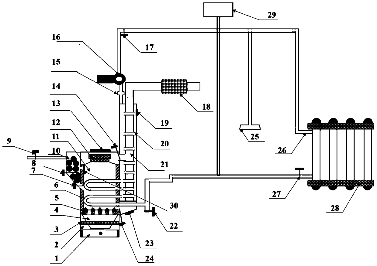
[0038] The ignition fuel is ignited in the furnace, and the biomass coal fuel is added to the fuel storage room 10 for low-temperature pyrolysis, and the pyrolysis gas inlet channel and the switch 9 are opened to allow the pyrolysis gas to enter the combustion chamber 11 for full combustion. Move left and right to move the airflow control plate 3 to adjust the size of the grid holes on the furnace body to increase the air intake appropriately, close the lower smoke control valve 24, open the upper smoke control valve 14 so that the flame is concentrated on the upper part of the combustion chamber 11, open The fire sealing cover 13 and the fire collecting cover 13 on the top of the gasification tray 12 are used as cooking purposes. The flue gas is only discharged through the passage where the upper flue gas control valve 14 is located. The double-layer hob and local pressurized structure make the airflow smoothly enter the combustion chamber 11 for combustion support, and the b...

Embodiment 2

[0040] The ignition fuel is ignited in the combustion chamber 11, and the biomass molding fuel is added to the fuel storage room 10 for low-temperature pyrolysis, and the pyrolysis gas recovery channel and switch 9 are opened to allow the pyrolysis to be stored in the storage tank through the booster pump to avoid incomplete combustion. Pollution emissions and energy waste. Move the airflow control plate left and right to adjust the size of the grid holes on the furnace body to appropriately reduce the air intake, and at the same time open the lower flue gas control valve 24 and the upper flue gas control valve 14 and close the top fire sealing cover and collector of the gasification tray 12. The fire hood 13 is used for heating. Due to the function of sealing the fire, a CO alarm needs to be installed to prevent danger from happening. At the same time, the smoke is discharged through the passage where the upper smoke control valve 14 and the lower smoke control valve 24 are lo...


PUM


Abstract

The invention discloses a clean and safe combustion system and method. The combustion system and method are suitable for household heating, cooking, bathing and the like. The system comprises a stove,a pyrolysis gas generation and utilization device and a flue gas purification and waste heat utilization device. The combustion system and method have the advantages that low-temperature pyrolysis offuels before combustion is realized, the energy waste and the environmental pollution are reduced, waste heat is used for water heating for indoor heating; the combustion system can realize effectiveutilization and clean combustion of various fuels such as low-quality coal and biomass waste, is suitable for various places such as rural areas, restaurants and thermal power plants and can be usedfor multiple purposes such as cooking, bathing and heating; and the manufacturing cost is low, the heat efficiency is high, the pollutant discharge is less, and the combustion system and method have important significance in realizing clean utilization of energy and urbanization in China.

Description

technical field [0001] The invention relates to a combustion system and method, especially a clean and safe combustion system and method suitable for household heating, cooking and bathing. Background technique [0002] The problem of scattered coal has been the focus of the government's work in recent years. At present, the problems of poor fuel quality and low efficiency of stoves are common in different regions of my country. Combustion systems that can achieve these goals are extremely important. [0003] In the process of implementing clean heating in rural areas in the northern region, the country has made instructions on fuel and stoves according to local conditions according to the actual situation of economic conditions and fuel supply in different regions. The method of adapting clean briquettes to energy-saving stoves has been proved to be a clean, efficient, and energy-saving means. The energy-saving and emission-reduction effect of water heating stoves is highe...

Claims


Application Information

Patent Timeline
IPC IPC(8): F24B9/00F24B13/00F23B90/06F24D15/00F23J15/02
CPCF24B9/00F24B13/00F23B90/06F24D15/00F23J15/02
Inventor 桂夏辉张鹏德
Owner CHINA UNIV OF MINING & TECH
Learn More