Cutting device for bottom of glass

A technology for cutting devices and glass cups, applied in glass cutting devices, glass manufacturing equipment, manufacturing tools, etc., can solve problems such as inconvenient replacement, maintenance and cleaning, non-adjustable, mismatched environment, etc., to achieve convenient replacement and disassembly rotation The effect of cutting sheets and improving work efficiency

Inactive Publication Date: 2019-11-08
蚌埠亘乐家庭用品有限公司
View PDF6 Cites 1 Cited by
  • Summary
  • Abstract
  • Description
  • Claims
  • Application Information

AI Technical Summary

Problems solved by technology

[0002] A traditional cutting device for the bottom of a glass, the internal structure is relatively fixed, the connection between the various components is a fixed connection, not adjustable, when facing different items and different places of use, it will be more or less The phenomenon does not match the environment, and the external construction is also relatively fixed, which is inconvenient to replace, maintain and clean
[0003] However, the currently used traditional cutting device for the bottom of the glass causes the user to more or less not match the size of the cut object when operating different cutting objects, resulting in that when working, The work cannot be completed in an effective and timely manner. If it is necessary to replace the cutting device, it is very troublesome to disassemble the device, which increases labor costs and time. Therefore, we propose a cutting device for the bottom of the glass

Method used


Image

  • Cutting device for bottom of glass
  • Cutting device for bottom of glass
  • Cutting device for bottom of glass

Examples


Embodiment Construction

[0024] In order to make the technical means, creative features, goals and effects achieved by the present invention easy to understand, the present invention will be further described below in conjunction with specific embodiments.

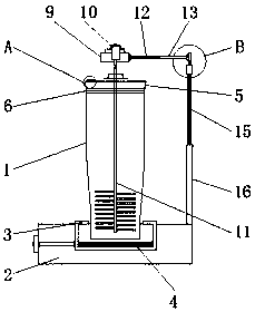
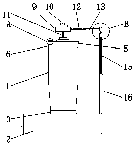
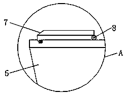
[0025] like Figure 1-4 As shown, a cutting device for the bottom of a glass includes a cup body 1, a cup cover 5, a cap 7, a connecting block 9, a rotary cutting piece 11 and a vertical rod 16, and a base 2 is provided under the cup body 1, and A fixed card slot 3 is installed above the base 2, a spring leaf 4 is installed below the fixed card slot 3, a cup cover 5 is arranged above the cup body 1, and a sealing mesh ring 6 is provided under the inner wall of the cup cover 5, and a cap 7 is provided On the left side above the cup cover 5, and the right side of the cap 7 is provided with a connecting pipe 8, the connecting block 9 is arranged on the top of the cup cover 5, and a motor 10 is installed on the top of the connecting block 9, and the r...


PUM


Abstract

The invention discloses a cutting device for the bottom of a glass. The cutting device comprises a glass body, a glass cover, a glass cover cap, a connecting block, a rotary cutting piece and a vertical rod, wherein a pedestal is arranged below the glass body; a fixed snapping groove is mounted on the pedestal; a spring leaf is mounted below the fixed snapping groove; the glass cover is arranged on the glass body, and a sealing mesh ring is arranged below the inner wall of the glass cover; the glass cover cap is arranged above the left side of the glass cover; a connecting pipe is arranged atthe right side of the glass cover cap; the connecting block is arranged above the glass cover; and a motor is mounted above the connecting block. According to the cutting device for the bottom of theglass, the fixed snapping groove is arranged and can be adjusted to the state of snapping with the outer wall of the glass body in virtue of the spring leaf, so the glass body can be fixed stationarily; and thus, the glass body is prevented from shaking due to shaking of the device during operation, and a user is thus prevented from inconvenience in operation of the device.

Description

technical field [0001] The invention relates to the related technical field of glasses, in particular to a cutting device for the bottom of a glass. Background technique [0002] A traditional cutting device for the bottom of a glass, the internal structure is relatively fixed, the connection between the various components is a fixed connection, not adjustable, when facing different items and different places of use, it will be more or less The phenomenon does not match the environment, and the external construction is also relatively fixed, which is inconvenient to replace, maintain and clean. [0003] However, the currently used traditional cutting device for the bottom of the glass causes the user to more or less not match the size of the cut object when operating different cutting objects, resulting in that when working, If the work cannot be completed in an effective and timely manner, it is very troublesome to disassemble the cutting device when the cutting device nee...

Claims


Application Information

Patent Timeline
IPC IPC(8): C03B33/06C03B33/10
CPCC03B33/06C03B33/105
Inventor 康闯朝殷宪鑫
Owner 蚌埠亘乐家庭用品有限公司
Why Eureka
Try Eureka