
Collaborative optimization configuration method for current limiting reactors and fault current limiters in flexible DC network

A technology of current-limiting reactors and fault current limiters, which is applied in the direction of emergency protection circuit devices, circuit devices, emergency protection circuit devices, etc. for limiting overcurrent/overvoltage, and can solve the problem of lack of effective and reliable theoretical methods, Problems such as weak flow resistance and inability to achieve global optimal configuration

Active Publication Date: 2019-11-05
SOUTHEAST UNIV
View PDF2 Cites 7 Cited by
  • Summary
  • Abstract
  • Description
  • Claims
  • Application Information

AI Technical Summary

Problems solved by technology

However, this solution currently faces two problems: 1) With the development of DC systems towards high-voltage and large-capacity, the development of corresponding high-voltage and large-capacity DC circuit breakers is restricted by the current technical background and investment costs
2) The insulated gate bipolar transistor (IGBT) in the converter valve has weak current resistance capability. Once the fault current of the MMC bridge arm exceeds the over-current protection threshold of the converter valve, the MMC will be blocked to protect the IGBT, causing a fault The scope of the spread is expanded, which is contrary to the original intention of using DC circuit breakers to quickly isolate faults in the flexible DC power grid
At present, the collaborative configuration of CLR and FCL in the flexible DC grid still lacks an effective and reliable theoretical method. Although a configuration scheme that meets the conditions can be found by using simulation, it cannot achieve the global optimal configuration.

Method used


Image

  • Collaborative optimization configuration method for current limiting reactors and fault current limiters in flexible DC network
  • Collaborative optimization configuration method for current limiting reactors and fault current limiters in flexible DC network
  • Collaborative optimization configuration method for current limiting reactors and fault current limiters in flexible DC network

Examples


specific Embodiment 1

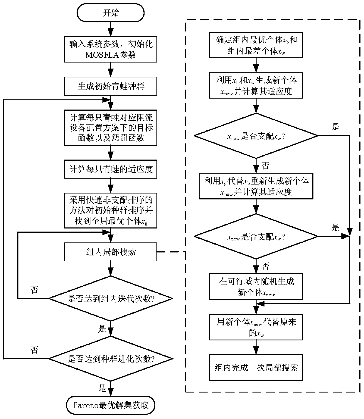
[0116] by figure 1 The shown four-terminal flexible DC grid based on MMC is taken as an example, combined with figure 2 Specifically, the specific steps of the collaborative optimization configuration method for the current-limiting reactor of the flexible DC power grid and the fault current limiter proposed by the present invention are described.

[0117] In the collaborative optimization configuration method proposed by the present invention, the multi-objective optimization configuration mathematical model is solved by MOSFLA, and the specific steps are as follows:

[0118] Step S1, input system parameters, initialize MOSFLA parameters:

[0119] (1) Input system parameters

[0120] When the MMC-based four-terminal flexible DC grid system is in normal operation, the first converter station MMC1 acts as the master control station to control the DC voltage to 500kV. The second converter station MMC2, the third converter station MMC3, and the fourth converter station MMC4 a...

specific Embodiment 2

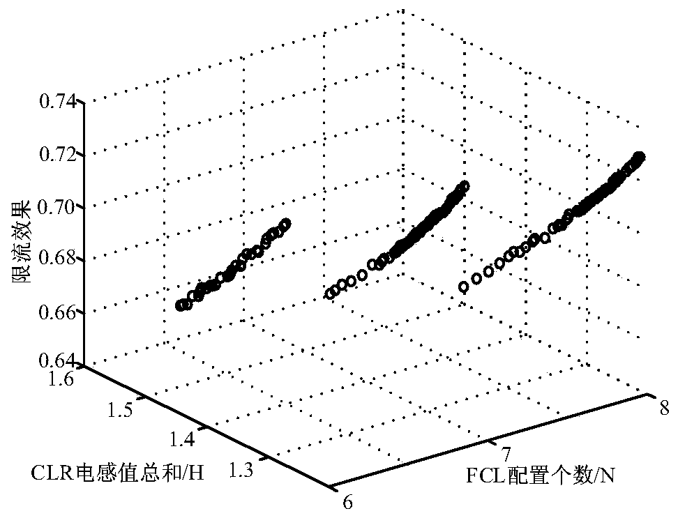
[0164] Taking scheme A in Table 2 as an example, the configuration scheme is shown in figure 1 In the shown four-terminal flexible DC grid, the first current-limiting reactor CLR 1 The inductance value is 0.161H, the second current limiting reactor CLR 2 The inductance value is 0.165H, the third current limiting reactor CLR 3 The inductance value is 0.168H, the fourth current limiting reactor CLR 4 The inductance value is 0.142H, the fifth current limiting reactor CLR 5 The inductance value is 0.169H, the sixth current limiting reactor CLR 6 The inductance value is 0.163H, the seventh current limiting reactor CLR 7 The inductance value is 0.155H, the eighth current limiting reactor CLR 8 The inductance value is 0.148H, and only the second fault current limiter FCL is configured 2 , the third fault current limiter FCL 3 , the fourth fault current limiter FCL 4 , the fifth fault current limiter FCL 5 , the seventh fault current limiter FCL 7 , the eighth fault current ...


PUM


Abstract

The invention relates to the technical field of flexible DC networks, in particular to a collaborative optimization configuration method for current limiting reactors and fault current limiters in a flexible DC network. A multi-objective optimization configuration mathematical model is established by comprehensively considering the performance of a system and the cost of current limiting equipmentand taking the current limiting effect, the total inductance value of the current limiting reactors and the quantity of the fault current limiters as objective functions and breaking current of DC circuit breakers, overcurrent protection of converter valves and the current limiting reactors as constraint conditions; the multi-objective optimization configuration mathematical model is solved by adopting a multi-objective shuffled frog-leaping algorithm to obtain an optimal solution set; and a proper configuration scheme is selected from the optimal solution set by combining the actual situation. According to the method, optimization configuration is carried out on the current limiting reactors and the fault current limiters in the flexible DC network, so that the global optimization objectives of the best current limiting effect, the minimum total inductance value of the current limiting reactors and the minimum installation number of the fault current limiters are achieved and continuous and stable operation of a health part of the flexible DC network in a fault can be ensured.

Description

technical field [0001] The invention relates to the technical field of flexible direct current power grids, in particular to a collaborative optimization configuration method for a current-limiting reactor and a fault current limiter in a flexible direct current power grid. Background technique [0002] The flexible DC power grid is an important direction for the development of modern power grids. The modular multilevel converter MMC has been widely used in flexible DC projects due to its advantages of less harmonic content, low switching frequency, and high reliability. Due to the low damping characteristics of the flexible DC grid, the DC fault develops rapidly and affects a wide range, which seriously threatens the safe and reliable operation of the system. Ensuring the survivability of the flexible DC grid under fault conditions is a key technical difficulty at present. [0003] The solution of configuring DC circuit breakers at both ends of the line is used to quickly ...

Claims


Application Information

Patent Timeline
Patent Type & Authority Applications(China)
IPC IPC(8): H02H9/02
CPCH02H9/021
Inventor 梅军范光耀葛锐王冰冰朱鹏飞严凌霄
Owner SOUTHEAST UNIV
Learn More