Small rod piece annealing machine tool

A rod and annealing technology, applied in the direction of furnace type, heat treatment equipment, furnace, etc., to achieve the effect of improving transmission stability, simple structure and stable transmission

Pending Publication Date: 2019-11-05
NANJING INST OF RAILWAY TECH
View PDF8 Cites 1 Cited by
  • Summary
  • Abstract
  • Description
  • Claims
  • Application Information

AI Technical Summary

Problems solved by technology

[0003] The purpose of the present invention is to solve the above-mentioned problems existing in the structure of the existing annealing machine tool, and propose an annealing machine tool designed for the annealing process of small rods, which can realize the automation of feeding and annealing processes

Method used


Image

  • Small rod piece annealing machine tool
  • Small rod piece annealing machine tool

Examples


Embodiment Construction

[0025] The technical solution of the present invention will be further described below according to the accompanying drawings.

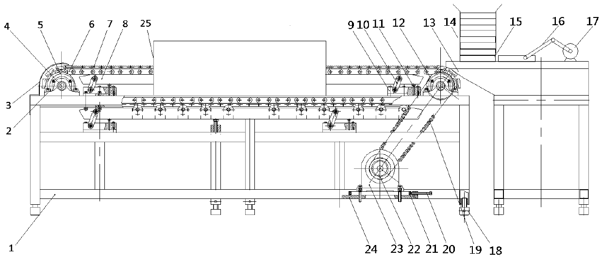
[0026] Such as figure 1 A small bar annealing machine tool is shown, its structure is divided into a feeding part and an annealing part, the feeding part is located on the right side of the annealing part, wherein the feeding part includes a feeding table 13, a blanking bin 14, a crank slide Block 16, A motor 17, wherein the blanking bin 14, the crank slider 16 and the A motor 17 are all arranged on the top of the loading table 13, the blanking bin 14 is installed on the end where the feeding part and the annealing part join, the crank slider The block 16 is located at the rear side of the blanking bin 14, and is connected with the A motor 17; the annealing part includes a frame 1, a driven sprocket 5, a double-pitch conveyor chain 6, a support frame 7, a driving sprocket 12, a deceleration Chain 19, B motor 22, speed reducer 23, seat plate 24, indu...


PUM


Abstract

The invention provides a small rod piece annealing machine tool. The small rod piece annealing machine tool structurally comprises a machine frame, a driven chain wheel, a double pitch conveying chain, a material bearing frame, a drive chain wheel, a loading platform, a feeding bin, a crank slide block, an electromotor A, a deceleration chain, an electromotor B, a deceleration machine and a seat plate. The small rod piece annealing machine tool adopts chain transmission in a main body transmission mechanism, and is simple in structure and stable in transmission; achieves a bearing function through a bearing plate mechanism, and prevents the defect that a chain droops due to the gravity in the transmission process, and then conveying efficiency is influenced; simultaneously replaces a tensioning wheel mechanism in a traditional machine tool, and can adjust the tightness degree of a transmission chain through adjustment of an arm plate; and uses a deep groove ball bearing to replace an idler wheel, thereby reducing friction and vibration, and improving transmission stationarity.

Description

technical field [0001] The invention provides a small bar annealing machine tool, which belongs to the technical field of metal processing equipment. Background technique [0002] Annealing refers to the process of slowly heating the metal to a certain temperature, keeping it for a sufficient time, and then cooling it at an appropriate speed. It is a widely used metal heat treatment process. Its purpose is to reduce the hardness of the metal and improve the machinability; Stress, stable size, reducing deformation and crack tendency of metal materials. With the development and popularization of industrial automation, the annealing process is also developing towards automation. At present, the annealing machine tool used in automatic annealing is a special machine tool equipment. By installing an induction device, the annealing process can be automatically controlled and enhanced. Process continuity, improving production efficiency. At present, the research and development o...

Claims


Application Information

Patent Timeline
IPC IPC(8): C21D1/26C21D9/00
CPCC21D1/26C21D9/0075
Inventor 周培
Owner NANJING INST OF RAILWAY TECH
Why Eureka
Try Eureka