Improved TD chain clamp device, working method thereof and wet diaphragm production line
An improved chain clip technology, applied to workpiece clamping devices, manufacturing tools, electrical components, etc., can solve problems such as increased workload, difficult handling, and reduced production efficiency, so as to achieve fixation and loosening, and improve movement The effect of stability and structure simplification
- Summary
- Abstract
- Description
- Claims
- Application Information
AI Technical Summary
Problems solved by technology
Method used
Image
Examples
Embodiment 1
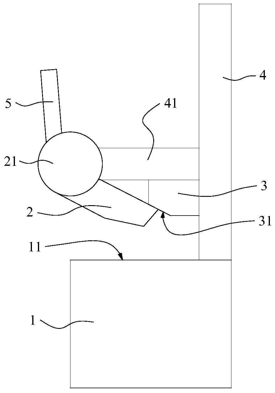
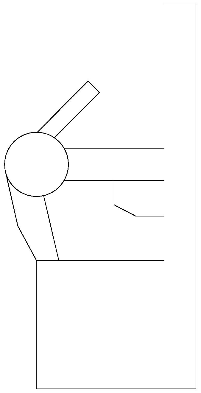
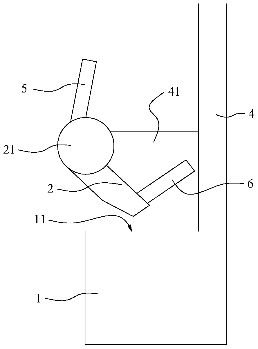
[0022] Such as Figure 1a and Figure 1b As shown, this embodiment 1 provides an improved TD chain clip device, including: a base 1 provided with a diaphragm station 11, a TD chain clip 2 located above the two sides of the diaphragm station 11, and a limit block 3 ; The TD chain clip 2 is suitable for being on the surface of the limit block 3 in the open state. At this time, the TD chain clip maintains a certain opening angle, about 30°, so that the TD chain clip can have enough height space to Release the diaphragm.
[0023] In this embodiment 1, Figure 2a and Figure 2b It does not represent the structure of the existing TD chain clip, but only to highlight the difference between the improved TD chain clip device of this embodiment 1 and the existing technology in the limit block and its installation position, and it is also convenient to understand the improvement of this embodiment 1 Type TD chain clip device is in open or closed state.
[0024] The improved TD chain ...
Embodiment 2
[0030] On the basis of embodiment 1, this embodiment 2 provides a working method of an improved TD chain clip device, the TD chain clip in the improved TD chain clip device is suitable for abutting against the surface of the limit block, so as to be in In the open state, loosen the diaphragm.
[0031] For the specific structure and implementation process of the improved TD chain clip device, please refer to the related discussions of Embodiment 1, and details will not be repeated here.
Embodiment 3
[0033] On the basis of Example 1, this Example 3 provides a wet-process diaphragm production line, including: the improved TD chain clip device as described above; the improved TD chain clip device is suitable for using the TD chain clip to Lithium battery separator is stuck or loosened.
[0034] For the specific structure and implementation process of the improved TD chain clip device, please refer to the related discussions of Embodiment 1, and details will not be repeated here.
[0035] To sum up, the improved TD chain clip device and its working method, and the wet-process diaphragm production line touch the surface of the limit block through the TD chain clip to be in an open state, which effectively solves the problem that the limit rod follows the chain clip in the prior art. Moving together will cause the problem of scratching the edge of the diaphragm; at the same time, setting the TD chain clip and the limit block separately can also simplify the structure of the TD ...
PUM
 Abstract
Description
Claims
Application Information
 - R&D
- Intellectual Property
- Life Sciences
- Materials
- Tech Scout
- Unparalleled Data Quality
- Higher Quality Content
- 60% Fewer Hallucinations
Browse by: Latest US Patents, China's latest patents, Technical Efficacy Thesaurus, Application Domain, Technology Topic, Popular Technical Reports.
© 2025 PatSnap. All rights reserved.Legal|Privacy policy|Modern Slavery Act Transparency Statement|Sitemap|About US| Contact US: help@patsnap.com


