an air supply unit

A component and air supply technology, applied to pump components, parts of pumping devices for elastic fluids, non-variable pumps, etc., can solve problems such as occupying a large space, increase air flow, and facilitate drainage , the effect of improving liquidity

Active Publication Date: 2021-01-05
中合智腾建设有限公司
View PDF2 Cites 0 Cited by
  • Summary
  • Abstract
  • Description
  • Claims
  • Application Information

AI Technical Summary

Problems solved by technology

This type of air supply system is a process of directly circulating the air flow in the space where the fan blades are located. The size of the air flow is mostly realized by controlling the speed of the fan blades. For air supply equipment such as fans, the diameter of the fan blades is large. It occupies a relatively large space. Therefore, there is no relevant technology in existing equipment or products to reduce the diameter of the fan blade without affecting or increasing the air volume as much as possible.

Method used


Image

  • an air supply unit
  • an air supply unit
  • an air supply unit

Examples


Embodiment 1

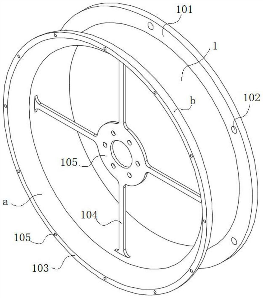
[0042]SeeFigure 1-2 As shown, the air supply assembly includes a first draft housing 1, a fan blade 5, a motor 4, a draft hood 3, and a second draft housing 2. The above-mentioned structural features constitute a basic structure. Both the first air induction shell 1 and the second air induction shell 2 are cylindrical structures.

[0043]SeeFigure 3-4 As shown, one end of the first air induction housing 1 is provided with a first arc-shaped cavity plate 103 extending outward. The first arc-shaped cavity plate 103 includes a first inner surface body a and a first outer surface body b; The end surface of the plate 103 is provided with an internal threaded hole 105; one end of the first draft housing 1 is also provided with a flange 101, and the end surface of the flange 101 is provided with a sealing groove 106 that cooperates with a sealing ring; A flange hole 102 is provided; the flange 101 at one end of the first air induction housing 1 can be used to cooperate with another air supply...

Embodiment 2

[0054]The overall structure is as shown in the first embodiment. In order to increase the wind power, another wind supply component can be superimposed. The basic stacking method is: based on the wind supply component shown in the first embodiment, add one end of the other wind supply component The draft hood 3 is removed, and at the same time, a flange is provided at one end of the second draft housing 2 for mating with the flange of the air supply assembly shown in the first embodiment, and more than one can be stacked in sequence.


PUM


Abstract

The invention discloses an air supply assembly, and relates to the technical field of mechanical equipment. The air supply assembly comprises a first air guide housing, fan blades, a motor, a draft hood and a second air guide housing, wherein one end of the first air guide housing is provided with a first arc-shaped cavity plate which extends outwardly, one end of the second air guide housing is provided with a second arc-shaped cavity plate which extends outwardly, and the second arc-shaped cavity plate comprises a second inner surface body and a second outer surface body. According to the air supply assembly, the first arc-shaped cavity plate and the second arc-shaped cavity plate form an inner surface which is in clearance fit with peripheral side rotating track surfaces of the fan blades, and during the rotation of the fan blades, air flow clearances are formed between the fan blade peripheral side rotating track surfaces, a first inner surface body and the second inner surface body to increase pressure, so that air pressure difference is generated on the two sides of each fan blade so as to increase the amount of air flow.

Description

Technical field[0001]The invention belongs to the technical field of mechanical equipment, and in particular relates to a wind supply assembly for providing wind power.Background technique[0002]Air supply components appear in various existing products, and generally appear in home appliances, such as hair dryers, fans, curling irons, etc. The air supply method is mostly driven by a motor and rotated to generate wind. Parts. This type of air supply system is a process of directly circulating the air flow in the space where the fan blades are located. The air flow is mostly achieved by controlling the speed of the fan blades. For air supply equipment such as fans, the fan blades have a large diameter. It takes up a lot of space. Therefore, if you want to reduce the diameter of the fan blade without affecting or increasing the air volume requirements as much as possible, there is no related technology in the existing equipment or products.[0003]Existing published document CN105310244A-...

Claims


Application Information

Patent Timeline
Patent Type & Authority Patents(China)
IPC IPC(8): F04D25/08F04D29/42F04D29/44F04D29/70F04D29/62
CPCF04D25/08F04D29/4226F04D29/441F04D29/626F04D29/703
Inventor 朱惜惜
Owner 中合智腾建设有限公司
Why Eureka
Try Eureka