Feeding structure and feeder

A feeder and material feeding technology, which is applied in the field of feeding structure and feeder, can solve the problems of material leakage, material jam, particle material leakage, etc., and achieve the effect of solving the problem of material leakage

Pending Publication Date: 2019-11-01
MANGO IOT CHANGZHOU CO LTD
View PDF0 Cites 0 Cited by
  • Summary
  • Abstract
  • Description
  • Claims
  • Application Information

AI Technical Summary

Problems solved by technology

[0005] The invention solves the problems of material leakage and material jamming in the related art, and proposes a feeding structure and a feeder, which can effectively solve the problems of material leakage and material jamming during the transfer of granular materials

Method used


Image

  • Feeding structure and feeder
  • Feeding structure and feeder
  • Feeding structure and feeder

Examples


Embodiment 1

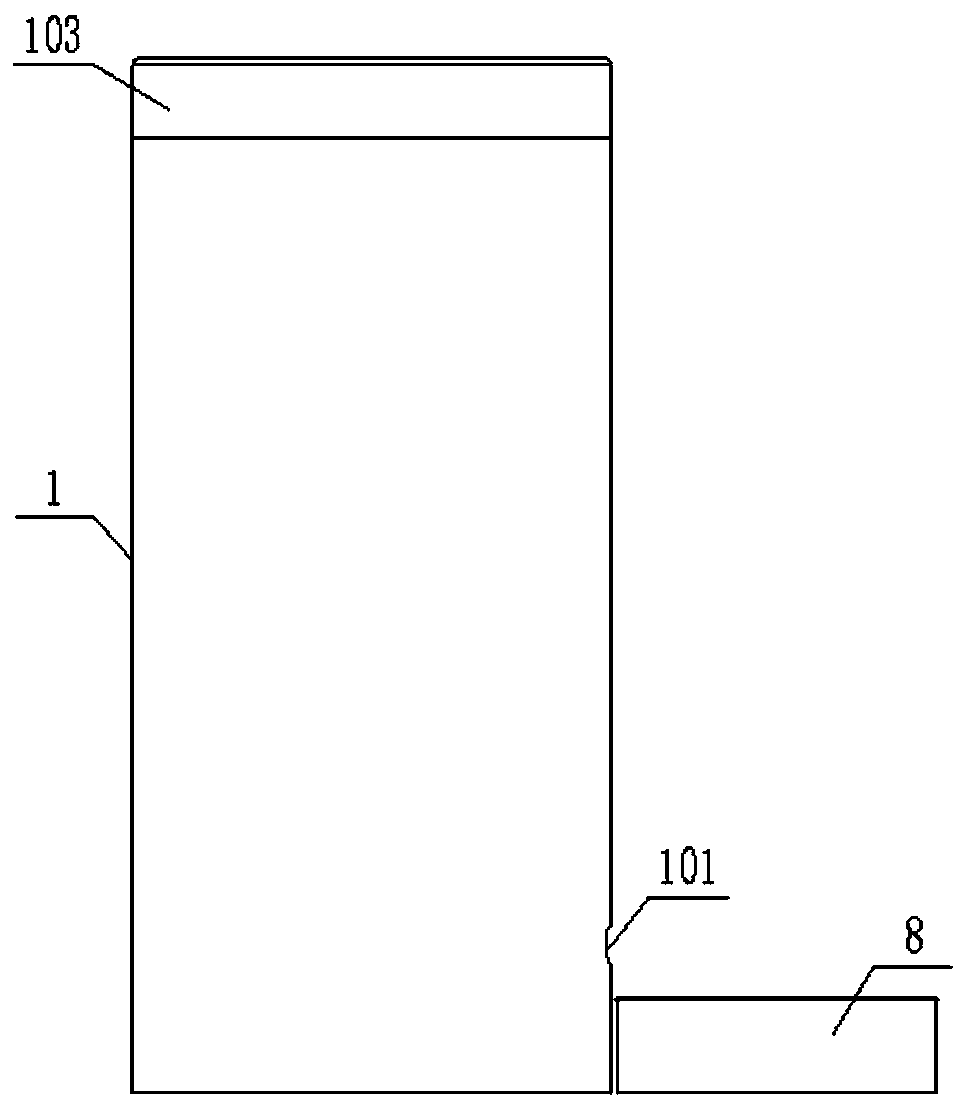
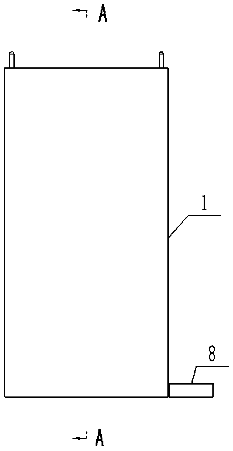
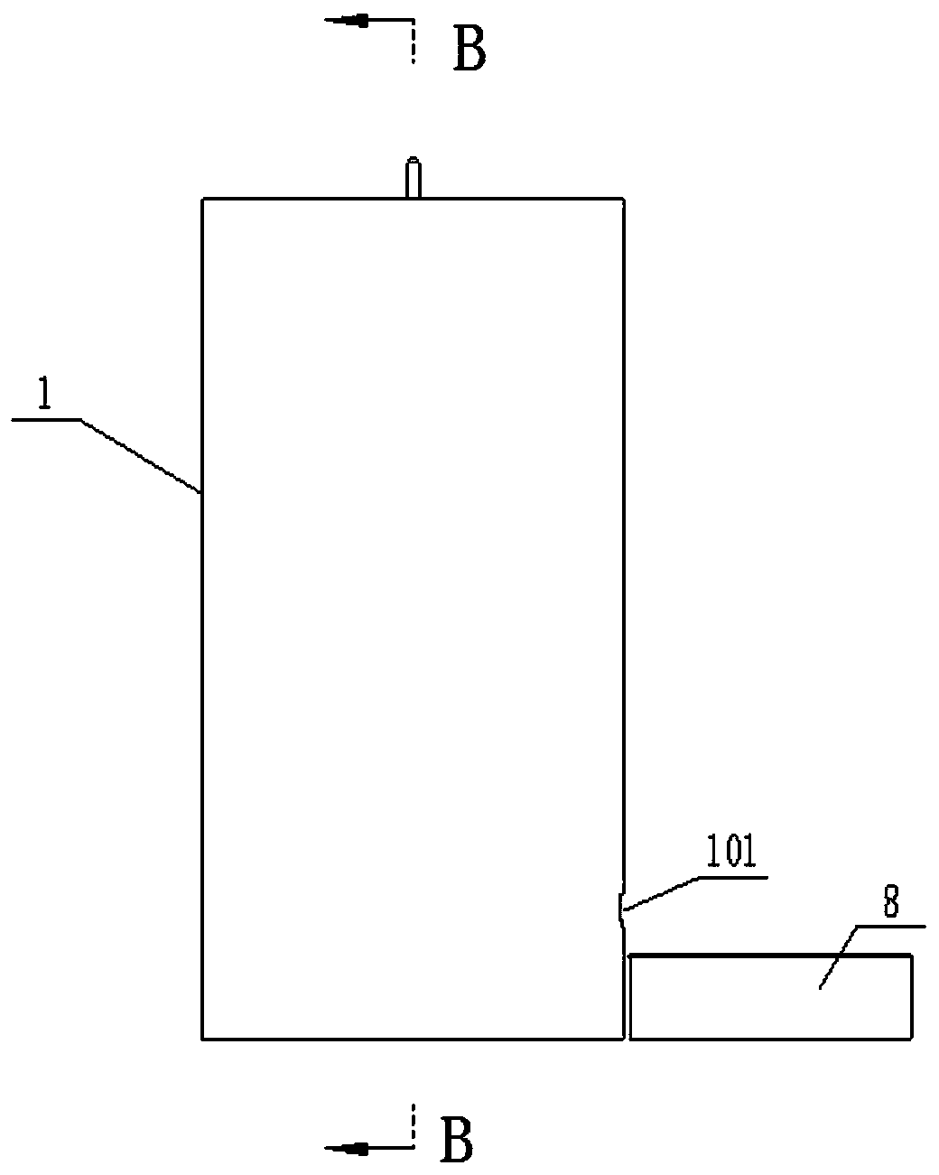
[0032] Such as Figures 1 to 6 As shown, a feeding structure includes a first cylinder body 1, a second cylinder body 2, a lifting disk 4 and a driving mechanism.

[0033] The lower part of the first cylinder 1 is provided with a discharge port 101, the upper end of the first cylinder 1 is open, the height of the first cylinder 1 is less than or equal to the height of the second cylinder 2, and an upwardly protruding end cap is installed on the opening 103 and the highest point of the end cover 103 is slightly higher than the second cylinder body 2, the end cover 103 has a restrictive effect on the material exposed from the upper end of the second cylinder body 2, so that the material can enter the material from the second cylinder body 2 The channel 3 will not spill out of the first cylinder 1; the first cylinder 1 is connected with a cross brace 102, and the cross brace 102 is fixedly connected with the upper end of the second cylinder 2.

[0034] Both ends of the second cy...

Embodiment 2

[0038] Such as Figures 1 to 6 As shown, a feeding structure includes a first cylinder body 1, a second cylinder body 2, a lifting disk 4 and a driving mechanism.

[0039] The lower part of the first cylindrical body 1 is provided with a discharge port 101, and one end of the first cylindrical body 1 is open, and the height of the first cylindrical body 1 is greater than the height of the second cylindrical body 2. At this time, the end cap 103 may not be installed, and the material Generally also can not be spilled out, also can install flat end cap 103 or the end cap 103 that protrudes upwards, has a restricting effect to the material that comes out from the second barrel 2 upper opening, can guarantee like this material from the second cylinder The body 2 enters the material channel 3 without spilling out of the first cylinder body 1; the first cylinder body 1 is connected with a cross brace 102, and the cross brace 102 is fixedly connected with the upper end of the second ...


PUM


Abstract

The invention relates to the technical field of feeding devices, in particular to a feeding structure and a feeder. The feeding structure comprises a first cylinder body, a second cylinder body, a lifting disc and a driving mechanism, one end of the first cylinder body is provided with an opening, and the lower portion of the first cylinder body is provided with a discharge opening; the two ends of the second cylinder body are opened, the second cylinder body is fixed in the first cylinder body, and a material passage is formed between the second cylinder body and the first cylinder body; thelifting disc is arranged in the second cylinder body; and the driving mechanism drives the lifting disc to move vertically in the second cylinder body. The feeder includes the feeding structure and adischarging plate, the discharging plate is inclined downwards, the upper end of the discharging plate is fixed to the inner wall of the first cylinder body and below the second cylinder body, and thelower end of the discharging plate is fixed to the inner wall of the first cylinder body and below the discharge port. The feeding structure is provided with the lifting disc, the lifting disc can bemoved up and down along the second cylinder body through a screw, and the problems of material leakage and material clamping can be effectively solved.

Description

technical field [0001] The invention relates to the technical field of feeding devices, in particular to a feeding structure and a feeder. Background technique [0002] The industrial field in the prior art usually involves the transfer and packaging of granular materials, but the existing transfer of granular materials has the following defects: [0003] First of all, the existing rotating blades for transporting granular materials cannot solve the problem of material leakage well. Since the rotating blades are made of soft plastic, when the cavity between two adjacent rotating blades is filled with materials, if the gravity of the materials Large deformation occurs on the rotating piece, which makes it unable to contact the blocking piece, and the material may leak from the gap between the blocking piece and the rotating piece. [0004] Secondly, the problem of material jamming cannot be solved well. Since the blocking piece is made of hard plastic and fixed on the top of...

Claims


Application Information

Patent Timeline
Patent Type & Authority Applications(China)
IPC IPC(8): B65G65/46B65D88/64
CPCB65D88/64B65G65/463
Inventor 田国林徐春丁萃储倩倩
Owner MANGO IOT CHANGZHOU CO LTD
Why Eureka
Try Eureka