
One-drive-two numerically controlled machining tool of multi-axis truss robot for large piston pin

A truss robot and piston pin technology, applied in metal processing and other directions, can solve problems such as reducing the production efficiency of enterprises, increasing production and processing time and staff workload, and cumbersome operations.

Active Publication Date: 2019-11-01
佛山市名将自动化设备有限公司
View PDF5 Cites 0 Cited by
  • Summary
  • Abstract
  • Description
  • Claims
  • Application Information

AI Technical Summary

Problems solved by technology

[0002] Piston pin CNC machine tools are used to manufacture and process piston pins. In the production process of piston pins, traditional piston pin CNC machine tools often use a piston pin CNC machine tool to process one end or a certain part of the piston pin, while the other end of the piston pin Or another part needs to be processed on another piston pin CNC machine tool. After processing from one piston pin CNC machine tool, it is necessary to manually collect the workpiece and transport the workpiece to another piston pin CNC machine tool for processing. Such operations are cumbersome and greatly Increase the production processing time and the workload of the staff, thereby reducing the production efficiency of the enterprise

Method used


Image

  • One-drive-two numerically controlled machining tool of multi-axis truss robot for large piston pin
  • One-drive-two numerically controlled machining tool of multi-axis truss robot for large piston pin
  • One-drive-two numerically controlled machining tool of multi-axis truss robot for large piston pin

Examples


Embodiment Construction

[0024] In the following, the present invention will be further described in conjunction with the accompanying drawings and specific embodiments, so as to understand more clearly the technical idea claimed in the present invention.

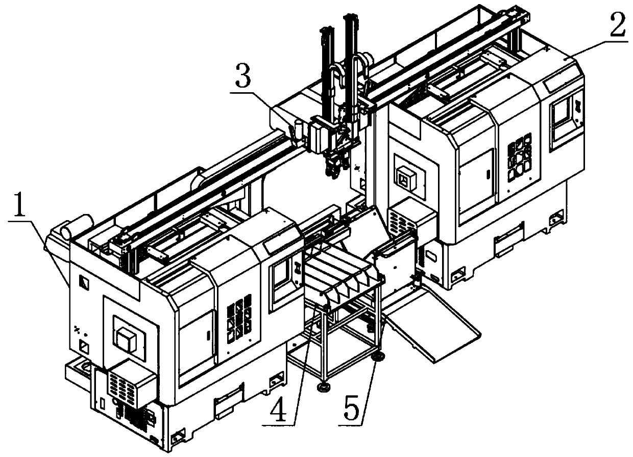
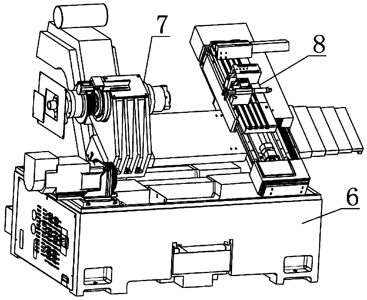
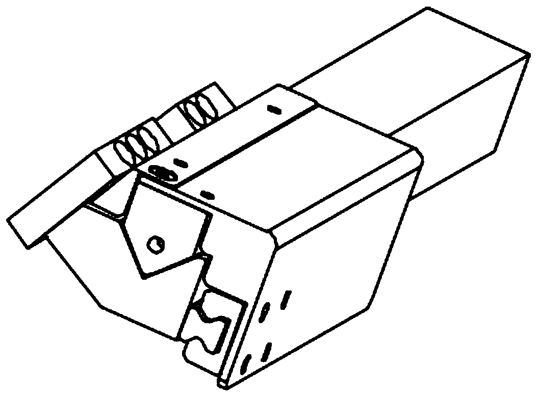
[0025] like Figures 1 to 9 As shown, a multi-axis truss robot one-to-two CNC machining machine for large piston pins, including a first piston pin CNC machine 1, a second piston pin CNC machine 2, a beam robot 3, a storage hoist 4 and a receiving storage machine 5. The first piston pin numerical control machine 1, the material storage hoist 4, the receiving storage machine 5 and the second piston pin numerical control machine 2 are arranged in sequence, and the first piston pin numerical control machine 1 and the second piston pin numerical control machine 2 are two All of them are equipped with a trough mechanism, and through the trough mechanism, the beam robot 3 is used to carry out the feeding and unloading work of the machine tool processing....


PUM


Abstract

The invention discloses a one-drive-two numerically controlled machining tool of a multi-axis truss robot for a large piston pin. The one drive two numerically controlled machining tool comprises a first piston pin numerically controlled machine, a second piston pin numerically controlled machine, cross beam robots, a storage lifter and a receiving storage machine. The first piston pin numericallycontrolled machine, the storage lifter, the receiving storage machine and the second piston pin numerically controlled machine are successively arranged, trough seats are arranged in both the first piston pin numerically controlled machine and the second piston pin numerically controlled machine which are matched with the cross beam robots through the trough seats for feeding and unloading work of machining tool machining, and the cross beam robots are separately mounted on the tops of the first piston pin numerically controlled machine and the second piston pin numerically controlled machineand clamp and convey materials among the first piston pin numerically controlled machine, the storage lifter, the receiving storage machine and the second piston pin numerically controlled machine. The one-drive-two numerically controlled machining tool of the multi-axis truss robot for the large piston pin can achieve automatic machining of the piston pin and improves the production efficiency of the piston pin.

Description

Technical field: [0001] The invention relates to the technical field of piston pin numerical control processing machine equipment, in particular to a multi-axis truss robot one-to-two numerical control processing machine for large piston pins. Background technique: [0002] Piston pin CNC machine tools are used to manufacture and process piston pins. In the production process of piston pins, traditional piston pin CNC machine tools often use a piston pin CNC machine tool to process one end or a certain part of the piston pin, while the other end of the piston pin Or another part needs to be processed on another piston pin CNC machine tool. After processing from one piston pin CNC machine tool, it is necessary to manually collect the workpiece and transport the workpiece to another piston pin CNC machine tool for processing. Such operations are cumbersome and greatly It increases the production and processing time and the workload of the staff, thereby reducing the production...

Claims


Application Information

Patent Timeline
Patent Type & Authority Applications(China)
IPC IPC(8): B23Q7/00B23Q7/04
CPCB23Q7/00B23Q7/04
Inventor 叶艳珍向良冯赞雄江文良
Owner 佛山市名将自动化设备有限公司
Learn More