An environmental protection building oil fume treatment device
A technology for oil fume treatment and construction, applied in the direction of separation method, dispersed particle separation, chemical instruments and methods, etc., can solve the problems of oil fume pipe odor, oil leakage, etc., achieve the effect of reducing working pressure, reducing the amount of grease, and low cost
- Summary
- Abstract
- Description
- Claims
- Application Information
AI Technical Summary
Problems solved by technology
Method used
Image

Examples
Embodiment 1
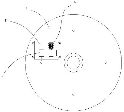
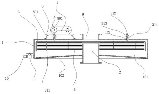
[0029] Embodiment 1: see figure 1 , figure 2 and image 3The shown environmental protection building oil fume treatment device includes a shell 1, an inner cavity 101 for intercepting oil fume is formed inside the shell 1, an inner tube 2 is welded at the bottom axis of the shell 1, and the inner tube 2 For passing oil fumes, the shell 1 has a conical inner bottom surface 102, which is welded with the inner tube 2 to form a seal, and the diameter of the inner bottom surface 102 gradually decreases upwards, and a flow baffle is arranged inside the shell 1 3. The windshield 3 is a cylinder with a closed upper end and an opening at the lower end. The upper end of the inner tube 2 extends into the windshield 3 , at the inner top of the windshield 3 A plurality of vertical shafts 311 are arranged in a ring, and the vertical shafts 311 and the spoiler 3 are welded and fixed, and a plurality of oil collecting plates 4 are assembled through the plurality of vertical shafts 311, and...
Embodiment 2
[0030] Embodiment 2: The oil collecting plate 4 and the vertical shaft 311 are fixed by welding.
Embodiment 3
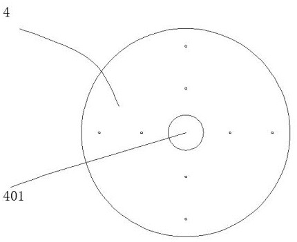
[0031] Embodiment 3: see Figure 4 As shown, the oil collecting plate 4 is composed of upper and lower sub-plates 411, bolts 412 are installed between the two sub-plates 411, and a fixed bin 413 is formed after the two sub-plates 411 are combined. After the sub-board 411 is combined, a plurality of oil spill holes 414 communicating with the fixed warehouse 413 are arranged on the outer surface of the block, and pores 415 are evenly distributed on the surface of the sub-board 411, and the pores 415 are inserted There are steel wools 416, one end of a plurality of steel wools 416 located in the same pore 415 is wound, and is clamped in the fixed bin 413 after winding, and the other end of the steel wools 416 extends to the outside of the pores 415 ; When the oil collecting plate is set up and down, the upper and lower adjacent steel wools are in contact with each other, the number of steel wools inserted in each pore is 20~60, and the wire diameter of the steel wools is 0.15mm. ...
PUM
| Property | Measurement | Unit |
|---|---|---|
| thickness | aaaaa | aaaaa |
| diameter | aaaaa | aaaaa |
| diameter | aaaaa | aaaaa |
Abstract
Description
Claims
Application Information
 - Generate Ideas
- Intellectual Property
- Life Sciences
- Materials
- Tech Scout
- Unparalleled Data Quality
- Higher Quality Content
- 60% Fewer Hallucinations
Browse by: Latest US Patents, China's latest patents, Technical Efficacy Thesaurus, Application Domain, Technology Topic, Popular Technical Reports.
© 2025 PatSnap. All rights reserved.Legal|Privacy policy|Modern Slavery Act Transparency Statement|Sitemap|About US| Contact US: help@patsnap.com