
Audio encoding and decoding circuit capable of avoiding generation of popping noise

An audio codec, popping technology, applied in transducer circuits, microphones, electrical components, etc., can solve the problems of loudspeaker popping noise, active amplifier circuit output errors, unable to maintain bias points, etc., to reduce the possibility, The effect of avoiding noise

Active Publication Date: 2019-10-29
REALTEK SEMICON CORP
View PDF5 Cites 0 Cited by
  • Summary
  • Abstract
  • Description
  • Claims
  • Application Information

AI Technical Summary

Problems solved by technology

At this time, the active amplifying circuit may not be able to maintain the correct bias point due to the floating state of the signal input terminal, and the signal input terminal of the active amplifying circuit may also receive various capacitive coupling or noise generated by inductive effects
[0004] In this way, it will cause the active amplifier circuit to output wrong signals to the speaker of the subsequent stage, which will cause the speaker to produce an annoying phenomenon of pop-noise (pop-noise)

Method used


Image

  • Audio encoding and decoding circuit capable of avoiding generation of popping noise
  • Audio encoding and decoding circuit capable of avoiding generation of popping noise

Examples


Embodiment Construction

[0026] Embodiments of the present invention will be described below in conjunction with related drawings. In the drawings, the same reference numerals represent the same or similar elements or method flows.

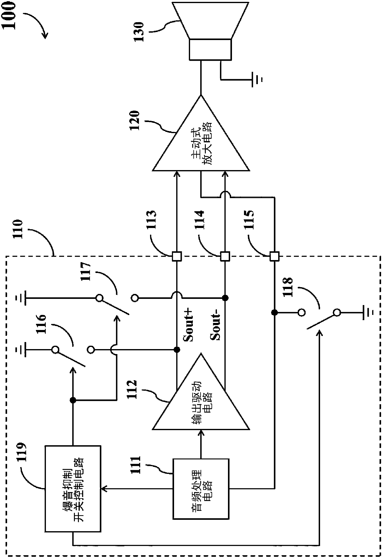
[0027] figure 1 It is a simplified functional block diagram of the audio playback device 100 according to an embodiment of the present invention. The audio playback device 100 includes an audio codec circuit 110 , an active amplifier circuit 120 , and a speaker 130 .

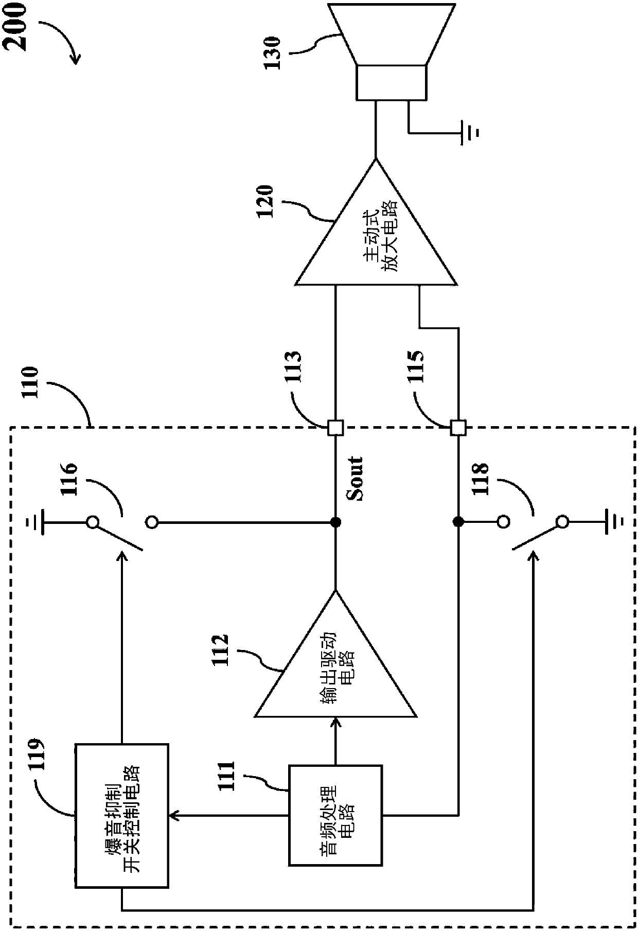
[0028] Such as figure 1 As shown, the audio codec circuit 110 includes an audio processing circuit 111, an output driver circuit 112, a first analog signal pin 113, a second analog signal pin 114, a multi-function signal pin 115, at least one popping sound Suppression switch, and a popping suppression switch control circuit 119 .

[0029] In the audio codec circuit 110 , the output driving circuit 112 is configured to generate a pair of differential analog output signals formed by the first analog signa...


PUM


Abstract

The invention provides an audio encoding and decoding circuit. The audio encoding and decoding circuit comprises an audio processing circuit; an output driving circuit used for generating an analog output signal according to the output of the audio processing circuit; an analog signal pin used for outputting the analog signal to an active amplifying circuit; a multifunctional signal pin used for providing different signal transmission functions according to the arrangement of the audio processing circuit; at least one popping suppression switch arranged between the analog signal pin and a first fixed potential end or between the multifunctional signal pin and a second fixed potential end; and a popping sound suppression switch control circuit coupled to the audio processing circuit and theat least one popping sound suppression switch, and arranged to control the at least one popping sound suppression switch according to the indication of the audio processing circuit.

Description

technical field [0001] The present invention relates to an audio codec circuit (audio codec circuit), in particular to an audio codec circuit which can avoid popping noise. Background technique [0002] Many audio playback devices use an active amplifier circuit to further amplify the analog signal generated by the audio codec circuit to drive the speaker in the subsequent stage. In most cases, the audio codec circuit and the active amplifier circuit belong to different circuit chips. [0003] Therefore, when the traditional audio codec circuit stops outputting signals due to entering the power-saving mode or being interrupted by the system, the active amplifier circuit in the subsequent stage may still be in a normal operating state. At this time, the active amplifying circuit may not be able to maintain the correct bias point due to the floating state of the signal input terminal, and the signal input terminal of the active amplifying circuit may also receive various capa...

Claims


Application Information

Patent Timeline
Patent Type & Authority Applications(China)
IPC IPC(8): H04R3/00
CPCH04R3/00H04R2410/05
Inventor 简志刚
Owner REALTEK SEMICON CORP
Learn More