
Suppression method for series compensation transformer direct current magnetic bias between micro-grid and power distribution network

A technology of DC bias suppression and series compensation, applied in the direction of AC network voltage adjustment, etc., can solve the problems of large effective material consumption, economical decline, large iron core cross-section, etc., to reduce manufacturing costs, solve inconvenient transportation, and reduce consumption Effect

Active Publication Date: 2019-10-29
TAIYUAN UNIV OF TECH
View PDF14 Cites 7 Cited by
  • Summary
  • Abstract
  • Description
  • Claims
  • Application Information

AI Technical Summary

Problems solved by technology

[0007] The purpose of the present invention is to solve the DC bias problem of the series compensation transformer caused by the rapid output of the series link voltage between the AC and DC microgrid and the distribution network. However, the prior art starts with the structural design of the series compensation transformer. This method will The cross-section of the iron core is too large, on the one hand, it consumes a lot of effective materials, on the other hand, when the transformer is running, the iron loss increases and the economy decreases

Method used


Image

  • Suppression method for series compensation transformer direct current magnetic bias between micro-grid and power distribution network
  • Suppression method for series compensation transformer direct current magnetic bias between micro-grid and power distribution network
  • Suppression method for series compensation transformer direct current magnetic bias between micro-grid and power distribution network

Examples


Embodiment Construction

[0050] In order to illustrate the embodiment of the present invention or the technical solution in the prior art more clearly, the technical solution of the present invention will be described in detail below. Apparently, the described embodiments are only some of the embodiments of the present invention, not all of them. Based on the embodiments of the present invention, all other implementations obtained by persons of ordinary skill in the art without making creative efforts fall within the protection scope of the present invention.

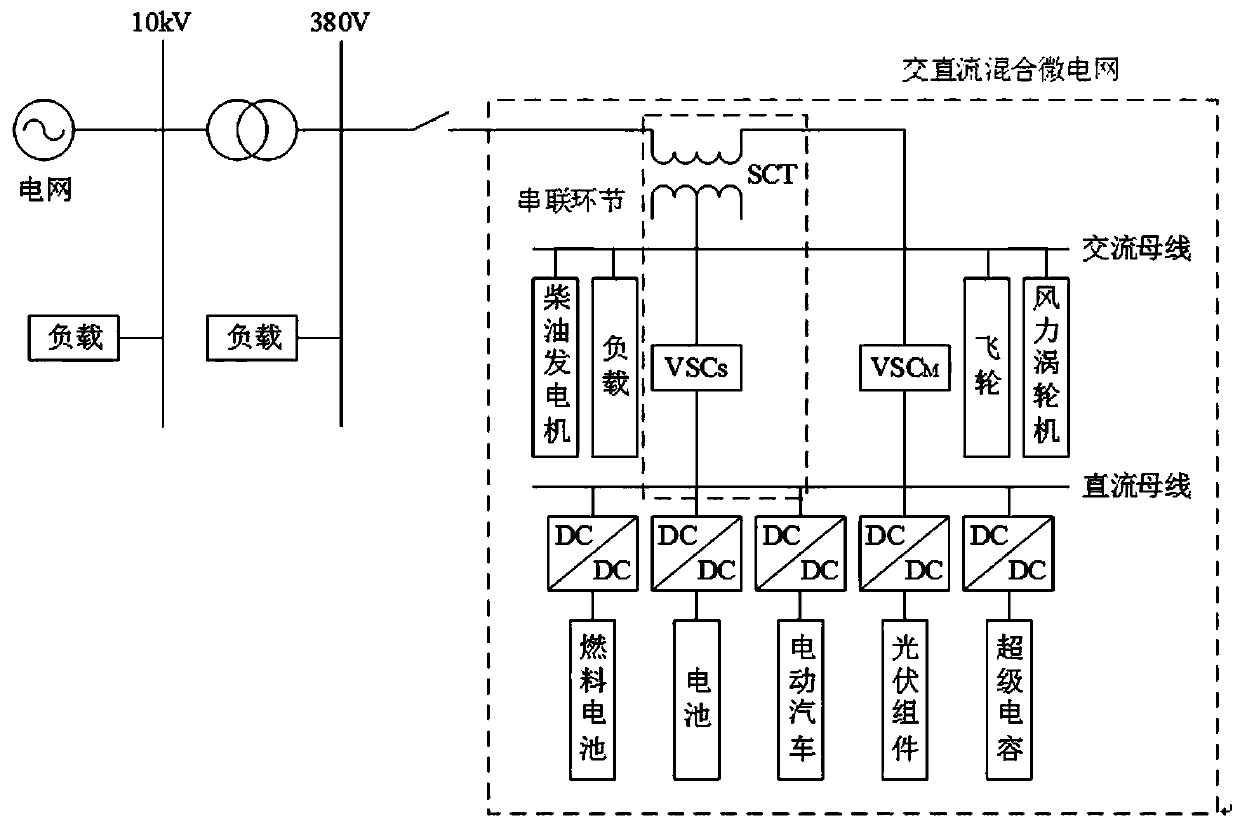
[0051] See attached Figure 1-Figure 17 , the DC bias suppression method of the series compensation transformer between the microgrid and the distribution network provided by the present invention will now be described.

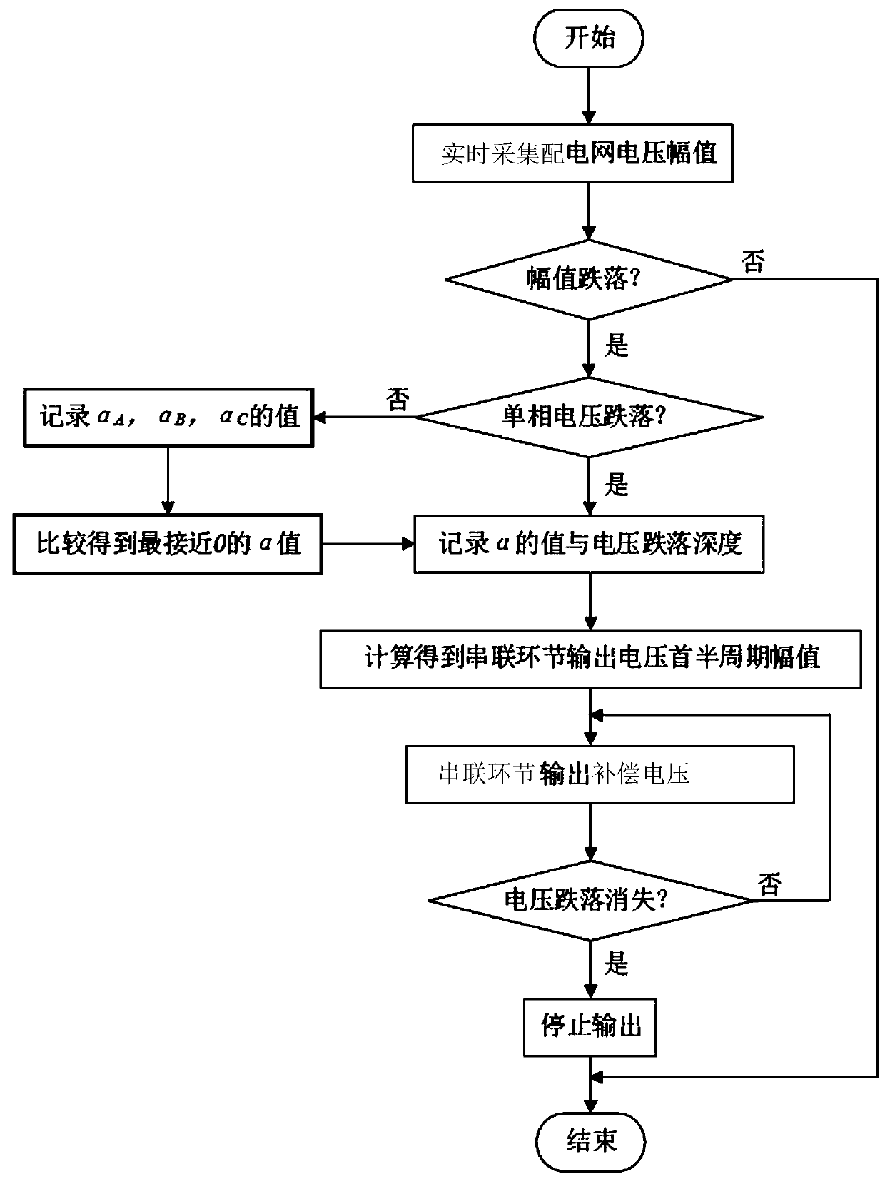
[0052] The DC bias suppression method of the series compensation transformer between the microgrid and the distribution network is as follows: image 3 shown, including the following steps:

[0053] S1: Detect and collect t...


PUM


Abstract

The invention belongs to the technical field of hybrid micro-grids and power distribution networks, and specifically relates to a suppression method for series compensation transformer direct currentmagnetic bias between a micro-grid and a power distribution network. Thus, the problems of series compensation transformer direct current magnetic bias between an alternating current / direct current micro-grid and a power distribution network caused by the rapid output of series link voltage can be solved. The method includes collecting the voltage amplitude of the power distribution network in real time; judging whether voltage dropping occurs, and recording alpha and voltage dropping depth; and calculating the first half period amplitude of compensation voltage and outputting the compensationvoltage until the voltage dropping disappears. The suppression on the series compensation transformer direct current magnetic bias under fault situations of single-phase voltage dropping and three-phase voltage dropping of a power grid can be realized, so that the normal operation of series links can be guaranteed, the normal operation of loads carried by an alternating current bus and the safetyof power electronic devices can be effective guaranteed, the fault ride-through capabilities of alternating current / direct current HMG on the voltage dropping of the power distribution network can beenhanced, and the power supply quality of the alternating current bus can be improved as well.

Description

technical field [0001] The invention belongs to the technical field of AC-DC hybrid micro-grid and distribution network, and specifically relates to a DC bias suppression method for a series compensation transformer between a micro-grid and a distribution network. Background technique [0002] AC / DC hybrid microgrid (hybrid micro-grid, HMG) usually has two operation modes: grid-connected mode and island mode. When operating in grid-connected mode, the AC / DC HMG is directly connected to the distribution network, and the distribution network provides voltage support for the AC bus of the AC / DC HMG. When a voltage drop occurs on the distribution network side, the AC bus voltage of the HMG will also change accordingly, which will inevitably affect the normal operation of the loads attached to the AC bus and threaten the safety of power electronic devices. In order to improve the fault ride-through capability of the AC / DC HMG to the voltage drop of the distribution network and i...

Claims


Application Information

Patent Timeline
Patent Type & Authority Applications(China)
IPC IPC(8): H02J3/12
CPCH02J3/12
Inventor 孟润泉韩肖清陈娟王子昂王磊秦文萍贾燕冰杜毅张鹏宇焦皎关正赵一潼翟晶晶
Owner TAIYUAN UNIV OF TECH
Learn More