
Clutch engagement assembly of door lock and driving device thereof

A technology for joining components and door locks, which is applied in the direction of preventing the key from being removed from the lock, the housing of the lock, door/window accessories, etc., which can solve problems such as incompatibility, reduced versatility, and reduced installation performance, and achieve smoothness Effects of improving operability and versatility

Pending Publication Date: 2019-10-29
ASSA ABLOY KOREA LTD
View PDF5 Cites 0 Cited by
  • Summary
  • Abstract
  • Description
  • Claims
  • Application Information

AI Technical Summary

Problems solved by technology

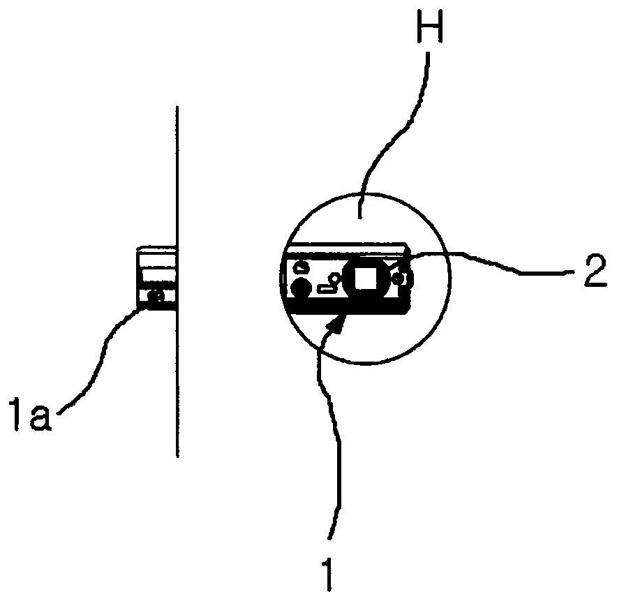
[0007] However, the conventional operation body 2 of the lever type door lock device has a disadvantage in that since the operation body 2 is installed outside the door D or inside the door lock body, it is difficult to miniaturize the device and its installation performance is reduced.
[0008] In addition, since some clutch devices applied to conventional lever-type door lock devices are manufactured exclusively therefor, these clutch devices are not compatible with other door lock devices, resulting in a problem of reduced versatility

Method used


Image

  • Clutch engagement assembly of door lock and driving device thereof
  • Clutch engagement assembly of door lock and driving device thereof
  • Clutch engagement assembly of door lock and driving device thereof

Examples


Embodiment 1

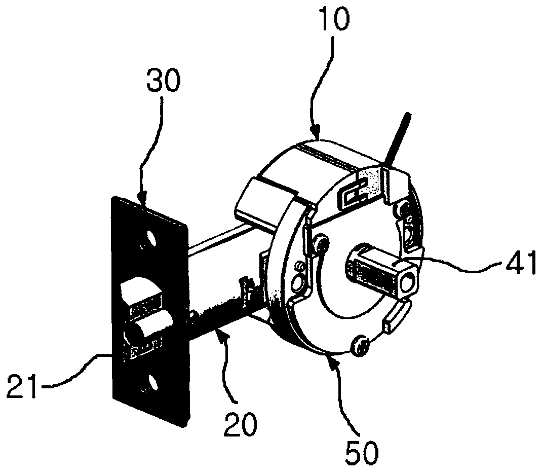
[0049] refer to Figure 2A and 2B , the latch operating body 20 is coupled to the driving module 50 . In the coupled state, the drive mass 50 is formed in the shape of a truncated disk. The motor unit 10 is placed on top of the driving module 50 , and the driving module 50 is generally formed in a disk shape in a state where the motor unit 10 is placed on the driving module 50 . In addition, a placement plate 30 is placed at an end of the latch operation body 20 , and the placement plate 30 is coupled and fixed to a side surface of the door D. As shown in FIG. In addition, the latch operation body 20 includes a latch door bolt 21 at an end thereof.

[0050] The drive module 50 and the motor unit 10 having the above structure are inserted into the circular mounting hole H of the door D by being coupled to each other (see Figure 1B ) to be installed.

[0051] refer to Figures 3A to 3C , the driving module 50 is provided with a pair of support parts 52 extending rearward ...

Embodiment 2

[0081] refer to Figure 15 and 16 , the loading module 50 includes a motor unit 10, a drive plate 60, a first shaft 41, a second shaft 42, and a pin clutch member (not assigned reference numerals).

[0082] The first shaft 41 and the second shaft 42 are installed so as to be arranged on the central axis of the loading module 50 . The motor unit 10 is loaded on an upper portion of the loading module 50 , and the motor unit 10 provides a driving force for rotating the driving plate 60 installed in the loading module 50 .

[0083] The drive plate 60 has an inner curved surface 64 on its inner side. The inner curved surface 64 has an inner cam surface 64a at a part thereof and a circular inner peripheral surface 64b at the other part thereof, wherein the inner cam surface 64a has a curvature smaller than the radius of curvature of the circular inner peripheral surface 64b. radius. An externally toothed gear 61 is formed at a part of the outer circumferential surface of the dri...


PUM


Abstract

A clutch engagement assembly for a door lock device includes a first shaft having at an end thereof an insertion end portion in which a channel is formed; a second drive shaft having a hollow engagement end portion into which the insertion end portion of the first shaft is inserted; a driving member which provides a driving force; and a pin member that is installed in a state of being elasticallysupported in the engagement end portion of the second shaft and is movable by the driving member so as to extending through (be inserted in) at least a part of the first shaft and at least a part of the second shaft, thereby causing a clutch engagement or a disengagement between a first shaft and a second shaft. The clutch engagement assembly may provide a relatively small size structure of the door lock device and a firm engagement force.

Description

technical field [0001] The present invention relates to a clutch joint assembly of a door lock device and a driving device for the clutch joint assembly thereof, more particularly to a clutch joint assembly of a door lock device and a clutch joint assembly to be installed to a lever type door lock device drive unit. Background technique [0002] In general, a lever type door lock device is a device in which a fixed bolt or a latch bolt is driven to lock and unlock a door by pivotally rotating a lever on an outdoor side or a lever on an indoor side. [0003] Such a lever-type door lock device includes a door lock capable of locking and unlocking a door only on an indoor side or a door lock capable of locking and unlocking a door on both sides of the door. [0004] Figure 1A and 1B It is a figure which shows the installation state of the conventional lever type door lock apparatus. [0005] refer to Figure 1A and 1B , in a conventional lever type door lock device, a moun...

Claims


Application Information

Patent Timeline
Patent Type & Authority Applications(China)
IPC IPC(8): E05B47/00E05B13/00
CPCE05B47/0012E05B47/0692E05B63/16E05B2047/002E05B2047/0021E05B1/003E05B9/04E05B13/005E05B13/101E05B15/00E05B15/0033E05B15/101E05B17/0054E05B17/044E05B27/0003E05B65/0811E05B81/46E05B2047/0026
Inventor 权泰勋
Owner ASSA ABLOY KOREA LTD
Learn More