Paper product printing machine with good heat dissipation performance

A heat dissipation performance and printing machine technology, which is applied to printing machines, rotary printing machines, general parts of printing machinery, etc., can solve the problems of high load of printing machines, different mechanical forms, and inconvenient printing work, etc., and achieve heat dissipation performance Good results

Inactive Publication Date: 2019-10-29
安徽文博纸品印刷有限公司
View PDF8 Cites 0 Cited by
  • Summary
  • Abstract
  • Description
  • Claims
  • Application Information

AI Technical Summary

Problems solved by technology

[0002] Printing machinery is a general term for mechanical equipment such as printing machines, binding machines, plate-making machines, and other auxiliary mechanical equipment. These mechanical equipment have different performances and uses. Therefore, the mechanical forms that make up them are not exactly the same. During work, the heat generated by the machine itself will cause the printing machine to run at high load. In severe cases, the components of the printing machine will be burned. At present, the traditional printing machine has the defect of poor heat dissipation, which brings inconvenience to the printing work. , affecting the heat dissipation of the printing press, thereby reducing the practicability of the printing press

Method used


Image

  • Paper product printing machine with good heat dissipation performance
  • Paper product printing machine with good heat dissipation performance
  • Paper product printing machine with good heat dissipation performance

Examples


Embodiment

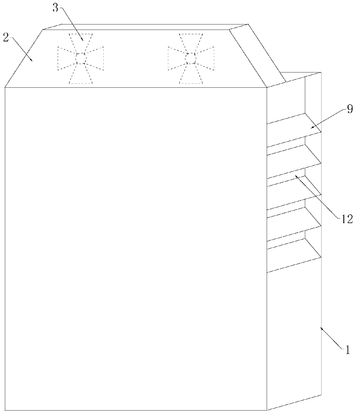
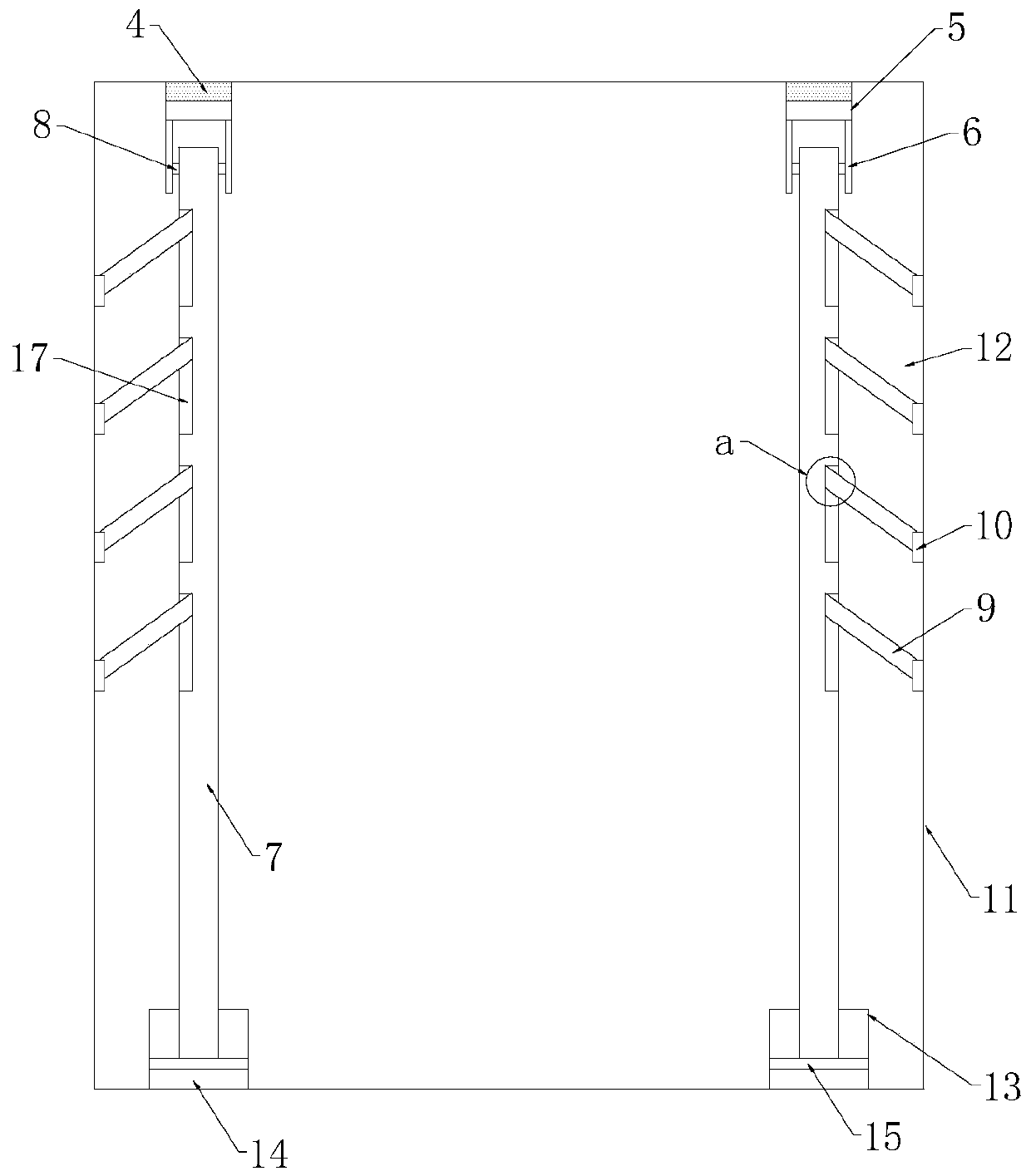
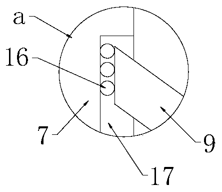
[0022] Example: such as Figure 1-3 As shown, a paper printing machine with good heat dissipation performance includes a printing machine body 1, a heat dissipation mounting plate 2 is installed on the printing machine body 1, a plurality of heat dissipation fans 3 are installed in the heat dissipation installation plate 2, and a plurality of heat dissipation fans 3 pass through the circuit The wire is connected to the contact switch 4 arranged on both sides of the printing machine body 1. The contact switch 4 is installed in the inner cavity of the guide cylinder 5. The guide plate 6 is fixed on both sides of the bottom of the guide cylinder 5, and the upper end of the temperature displacement roller 7 is covered. The set guide shaft 8 is slidingly connected to the chute embedded in the middle of the guide plate 6, and the temperature displacement roller 7 is provided with a number of adjustment chambers 17, one end of the cooling plate 9 is movably clamped in the adjustment c...


PUM


Abstract

The invention discloses a paper product printing machine with good heat dissipation performance. The paper product printing machine comprises a printing machine body, wherein heat dissipation mountingplates are arranged on the printing machine body, a plurality of heat dissipation fans are arranged inside the heat dissipation mounting plates, the plurality of heat dissipation fans are connected to a contact switch on two sides of the printing machine body through a circuit conductor, the contact switch is installed in the inner cavity of a guide cylinder, guide plates are fixedly arranged onthe two sides of the bottom of the guide cylinder, a guide shaft arranged at the upper end of a temperature displacement roller is slidably connected with embedded sliding grooves in the middles of the guide plates in a sliding mode, a plurality of adjusting cavities are formed in the temperature displacement roller, one end of the heat dissipation plates are movably clamped inside the adjusting cavities, the other end of the heat dissipation plates are fixedly installed on a cover plate through hinges, and a plurality of heat dissipation holes are formed in the cover plate, expansion air bagstorage cavities are arranged on the two sides of the bottom part of the printing machine body, expansion air bags are arranged inside the expansion air bag storage cavities, the tops of the expansionair bags are fixedly connected with a movable plate, and one end, away from the guide cylinder, of the temperature displacement roller is fixedly connected with the movable plate into a whole.

Description

technical field [0001] The invention relates to the technical field of printing equipment, in particular to a paper printing machine with good heat dissipation performance. Background technique [0002] Printing machinery is a general term for mechanical equipment such as printing machines, binding machines, plate-making machines, and other auxiliary mechanical equipment. These mechanical equipment have different performances and uses. Therefore, the mechanical forms that make up them are not exactly the same. During work, the heat generated by the machine itself will often cause the printing machine to run at a high load. In severe cases, the components of the printing machine will be burned. At present, the traditional printing machine has the defect of poor heat dissipation, which brings inconvenience to the printing work. , which affects the heat dissipation of the printing press, thereby reducing the practicability of the printing press. [0003] In order to solve the ...

Claims


Application Information

Patent Timeline
IPC IPC(8): B41F17/00B41F33/00F25D31/00
CPCB41F17/00B41F33/00F25D31/00
Inventor 李晓梅
Owner 安徽文博纸品印刷有限公司
Why Eureka
Try Eureka