
Profile material cutting device with automatic unloading function

An automatic unloading and cutting device technology, which is applied in the direction of sawing machine, manufacturing tools, metal sawing equipment, etc., can solve the problems of no unloading, low production efficiency, injury, etc., to avoid danger and reduce labor loss Effect

Active Publication Date: 2019-10-29
丽水市正明机械科技有限公司
View PDF4 Cites 3 Cited by
  • Summary
  • Abstract
  • Description
  • Claims
  • Application Information

AI Technical Summary

Problems solved by technology

[0002] Steel pipes are mainly used in petroleum, chemical, medical, food, light industry, mechanical instrumentation and other industrial pipelines and mechanical structural components. Mechanical parts and engineering structures are also often used as furniture and kitchen utensils. In the existing engineering or mechanical processing, steel pipes of different lengths are often used, and the integrally formed steel pipes have fixed lengths when they are cast. The cutting process needs to be used. Now the commonly used cutting device only has the function of cutting and has no function of unloading. Every time a cutting is completed, the steel pipe after cutting needs to be taken out manually, which must be repeated continuously during production. The process of starting up, producing, shutting down to pick up materials, restarting production, and shutting down to pick up materials again, because workers need to continuously pick up materials when picking up materials, the labor intensity of workers is high, production efficiency is low, and workers have to constantly Close to the cutting device to pick up the cut steel pipe at the blanking position, because it is very close to the cutter device, there is a great risk of injury

Method used


Image

  • Profile material cutting device with automatic unloading function
  • Profile material cutting device with automatic unloading function
  • Profile material cutting device with automatic unloading function

Examples


Embodiment Construction

[0024] The technical solutions of the present invention will be further described below in conjunction with the accompanying drawings and through specific implementation methods.

[0025] Wherein, the accompanying drawings are only for illustrative purposes, showing only schematic diagrams, rather than physical drawings, and should not be construed as limitations on this patent; in order to better illustrate the embodiments of the present invention, some parts of the accompanying drawings will be omitted, Enlargement or reduction does not represent the size of the actual product; for those skilled in the art, it is understandable that certain known structures and their descriptions in the drawings may be omitted.

[0026] In the drawings of the embodiments of the present invention, the same or similar symbols correspond to the same or similar components; , "inner", "outer" and other indicated orientations or positional relationships are based on the orientations or positional ...


PUM


Abstract

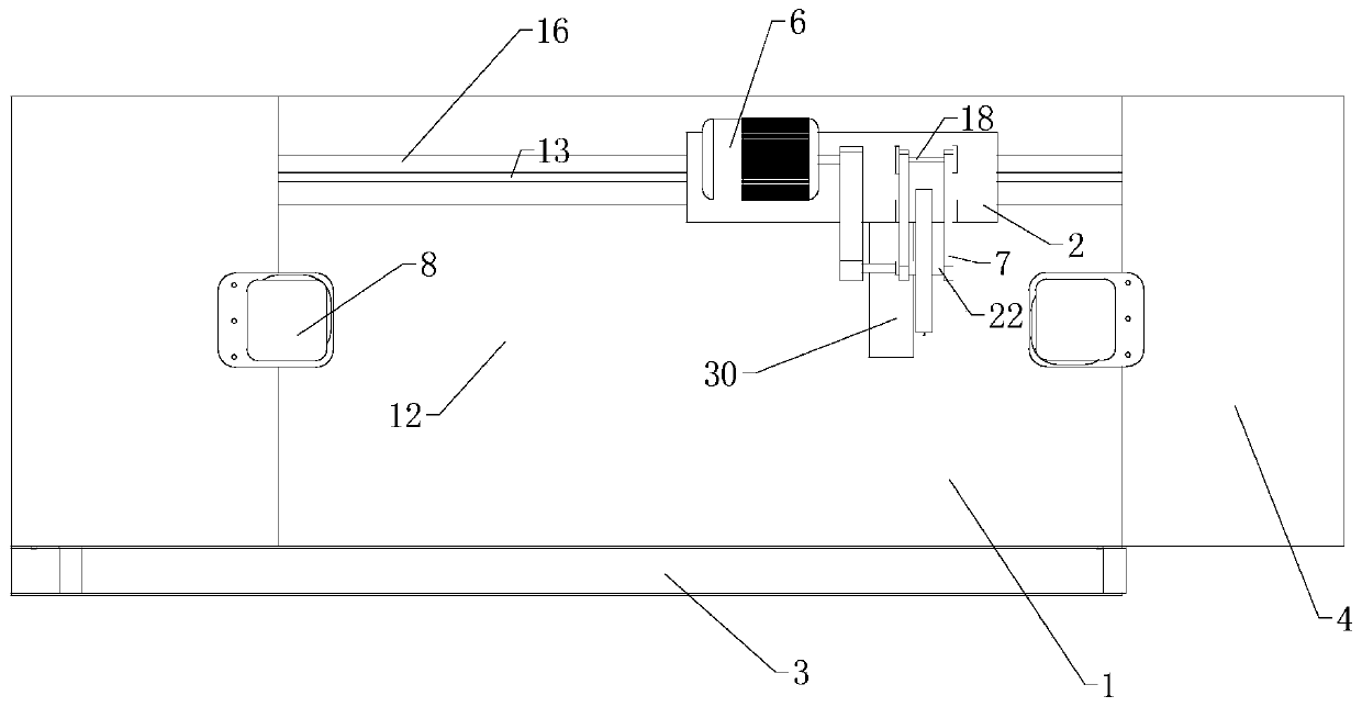
The invention relates to the field of mechanical cutting, in particular to a profile material cutting device with an automatic unloading function. The profile material cutting device comprises a workbench, a movable sliding table, a receiving conveying belt and two clamping mechanisms. Heightened parts are arranged at the two ends of the top of the workbench. The workbench is of a U-shaped structure overall. A disc saw blade, a rotary motor and a support arm are arranged at the top of the movable sliding table. Each clamping mechanism comprises a pipe frame, a pressing plate and a second air cylinder. The parts, under the two pipe frames, of the face of the workbench are of an inclined structure. During use, two ends of a steel pipe are put on the pipe frames, the second air cylinders drive the pressing plates to move downwards to tightly press and fix the two ends of the steel pipe, the disc saw blade conducts cutting, after the steel pipe is cut off, the second air cylinders drive the pressing plates to conduct loosening, and at the moment, the steel pipe loses central point support and slides onto the receiving conveying belt. Through the automatic unloading function of the clamping mechanisms, labor force loss of workers is lowered greatly, and risk possibly occurring during unloading is avoided.

Description

technical field [0001] The invention relates to the field of mechanical cutting, in particular to a profile cutting device with an automatic unloading function. Background technique [0002] Steel pipes are mainly used in petroleum, chemical, medical, food, light industry, mechanical instrumentation and other industrial pipelines and mechanical structural components. Mechanical parts and engineering structures are also often used as furniture and kitchen utensils. In the existing engineering or mechanical processing, steel pipes of different lengths are often used, and the integrally formed steel pipes have fixed lengths when they are cast. The cutting process needs to be used. Now the commonly used cutting device only has the function of cutting and has no function of unloading. Every time a cutting is completed, the steel pipe after cutting needs to be taken out manually, which must be repeated continuously during production. The process of starting up, producing, shuttin...

Claims


Application Information

Patent Timeline
Patent Type & Authority Applications(China)
IPC IPC(8): B23D45/12B23D47/04
CPCB23D45/12B23D47/04
Inventor 林迺建
Owner 丽水市正明机械科技有限公司
Learn More