
Diesel engine

A diesel engine and piston technology, applied in engine components, combustion engines, machines/engines, etc., can solve the problems of reduced fuel spray and air mixing, increased cooling loss, increased NOx, black smoke production, etc., to achieve Achieve cooling loss and improved mixing properties

Inactive Publication Date: 2019-10-25
MAZDA MOTOR CORP
View PDF8 Cites 0 Cited by
  • Summary
  • Abstract
  • Description
  • Claims
  • Application Information

AI Technical Summary

Problems solved by technology

Therefore, when the penetration of the spray is enhanced to improve the mixing of fuel spray and air in the medium and high load regions, the area where the combustion gas contacts the wall surface of the chamber becomes larger in the low load region, and the cooling loss increases. Large, so the fuel economy of the engine is reduced
[0009] On the other hand, when the penetration of the spray is weakened to reduce the cooling loss, the mixing property of the fuel spray and air decreases, and the generation of NOx and black smoke increases due to localized combustion

Method used


Image

  • Diesel engine
  • Diesel engine
  • Diesel engine

Examples


Embodiment Construction

[0040] Hereinafter, a diesel engine according to an embodiment of the present invention will be described with reference to the drawings.

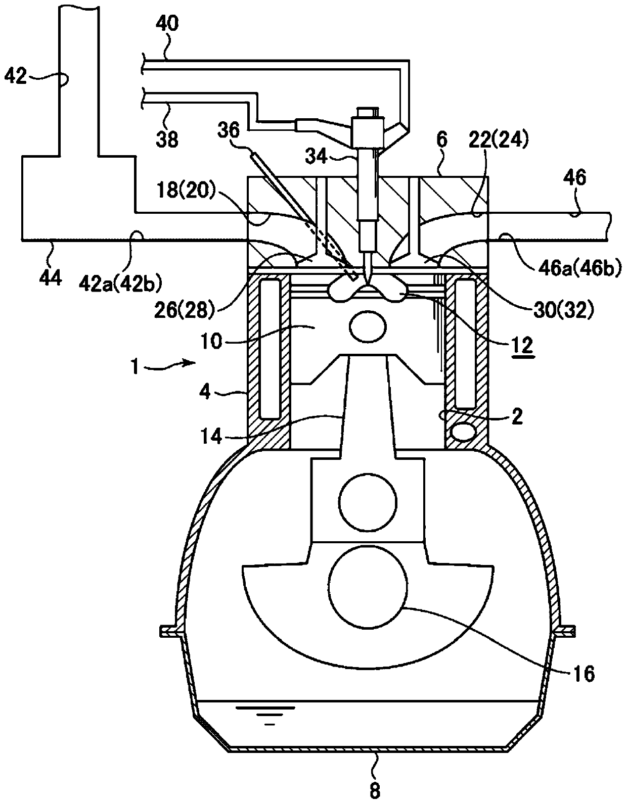
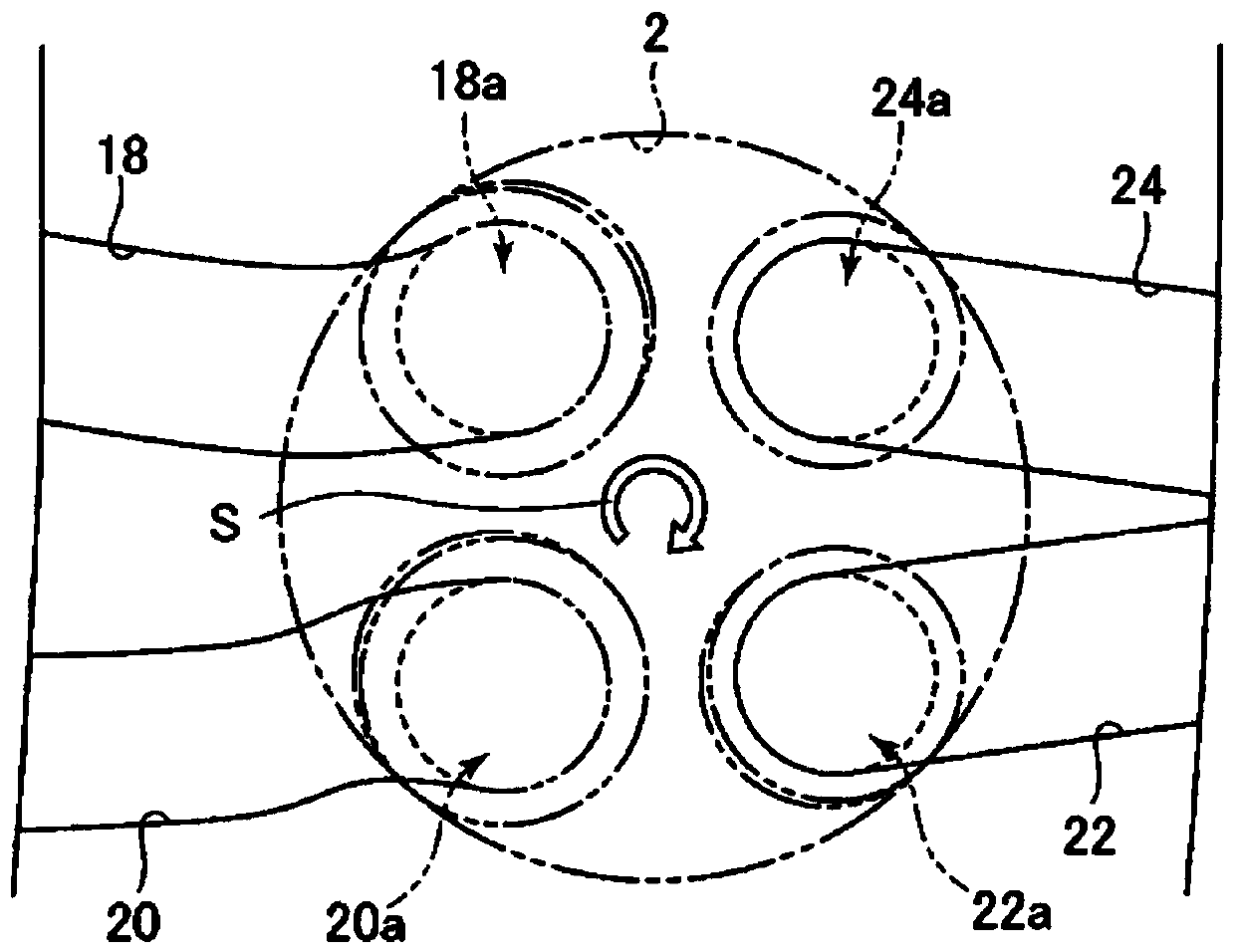
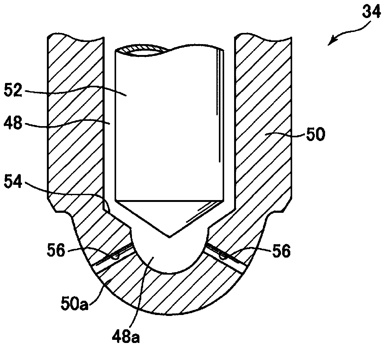
[0041] First, refer to Figure 1 to Figure 4 The structure of a diesel engine according to an embodiment of the present invention will be described.

[0042] figure 1 is a schematic diagram showing the structure of a diesel engine according to an embodiment of the present invention, figure 2 It is a top view schematically showing the arrangement of intake ports and exhaust ports in a diesel engine according to an embodiment of the present invention, image 3 is a partial cross-sectional view of a tip portion of a fuel injection valve according to an embodiment of the present invention, Figure 4 It is a diagram showing an example of a fuel injection method that is set differently depending on the operating state of the diesel engine according to the embodiment of the present invention.

[0043] exist figure 1 Among them, symbol 1 rep...


PUM


Abstract

Provided is a diesel engine capable of achieving both a reduction in cooling loss and an improvement in a fuel spray and air mixing performance, by increasing a movement distance of fuel spray in a cavity without strengthening penetration of the fuel spray. A diesel engine (1) includes: a cylinder head (6) covering one end of a cylinder (2); a piston (10) which is provided with a crown surface (10a) facing the cylinder head and which reciprocates inside the cylinder; and a fuel injection valve (34) attached to the cylinder head. A cavity (12) which is recessed toward the side opposite to the cylinder head and which is circular in a plan view is formed in the crown surface of the piston. An injection hole (56) directed into the cavity is formed in the fuel injection valve. A wall surface forming the cavity includes a wall portion (64) which is formed in a position, on a peripheral edge of the cavity, away from the direction in which the injection hole is directed, and which projects toward the radially inner side of the piston, substantially parallel to a plane including a central axis of the piston.

Description

technical field [0001] The present invention relates to a diesel engine, in particular to a diesel engine having the following structures: a cylinder head, which covers one end of the cylinder; the head is opposite; and a fuel injection valve mounted on the cylinder head. Background technique [0002] It is known that in a diesel engine, especially a small diesel engine used in a passenger car, a concave cavity is formed on the crown surface of the piston, that is, a cavity in which the central part is raised and the opening is narrowed into an upper narrowing shape (such as Refer to the following patent document 1). [0003] In a diesel engine such as Patent Document 1 in which a concave cavity is formed on a piston, when a fuel injection valve injects a large amount of fuel in a medium load region or a high load region of the engine, for example, the peripheral portion of the cavity may be reached. The flow of the fuel spray is reversed (ie, direction-switched toward the...

Claims


Application Information

Patent Timeline
Patent Type & Authority Applications(China)
IPC IPC(8): F02B23/06F02B23/10F02M61/14
CPCF02B23/06F02B23/10F02M61/14F02B23/0627F02B23/0687F02B23/0696F02B23/0669Y02T10/12F02B23/0672F02B2275/14F02F3/26
Inventor 神崎淳片冈一司金尚奎志茂大辅
Owner MAZDA MOTOR CORP
Learn More