
Fault positioning method, device and apparatus for startup process of server and storage medium

A fault location, server technology, applied in the fault hardware testing method, the use of power-on test to detect faulty hardware, and the detection of faulty computer hardware, etc., can solve problems such as long boot time, long serial port information export time, and slow fault location. To achieve the effect of shortening the export time, shortening the boot time, and improving the fault location speed

Inactive Publication Date: 2019-10-25
INSPUR SUZHOU INTELLIGENT TECH CO LTD
View PDF2 Cites 1 Cited by
  • Summary
  • Abstract
  • Description
  • Claims
  • Application Information

AI Technical Summary

Problems solved by technology

[0003] The most commonly used debugging method based on the input and output system is to set Token DEBUG_MODE to 1, and export the serial port information generated during the entire power-on self-test process. You can see the boot process and locate the fault. boot time too long

Method used


Image

  • Fault positioning method, device and apparatus for startup process of server and storage medium
  • Fault positioning method, device and apparatus for startup process of server and storage medium
  • Fault positioning method, device and apparatus for startup process of server and storage medium

Examples


Embodiment 1

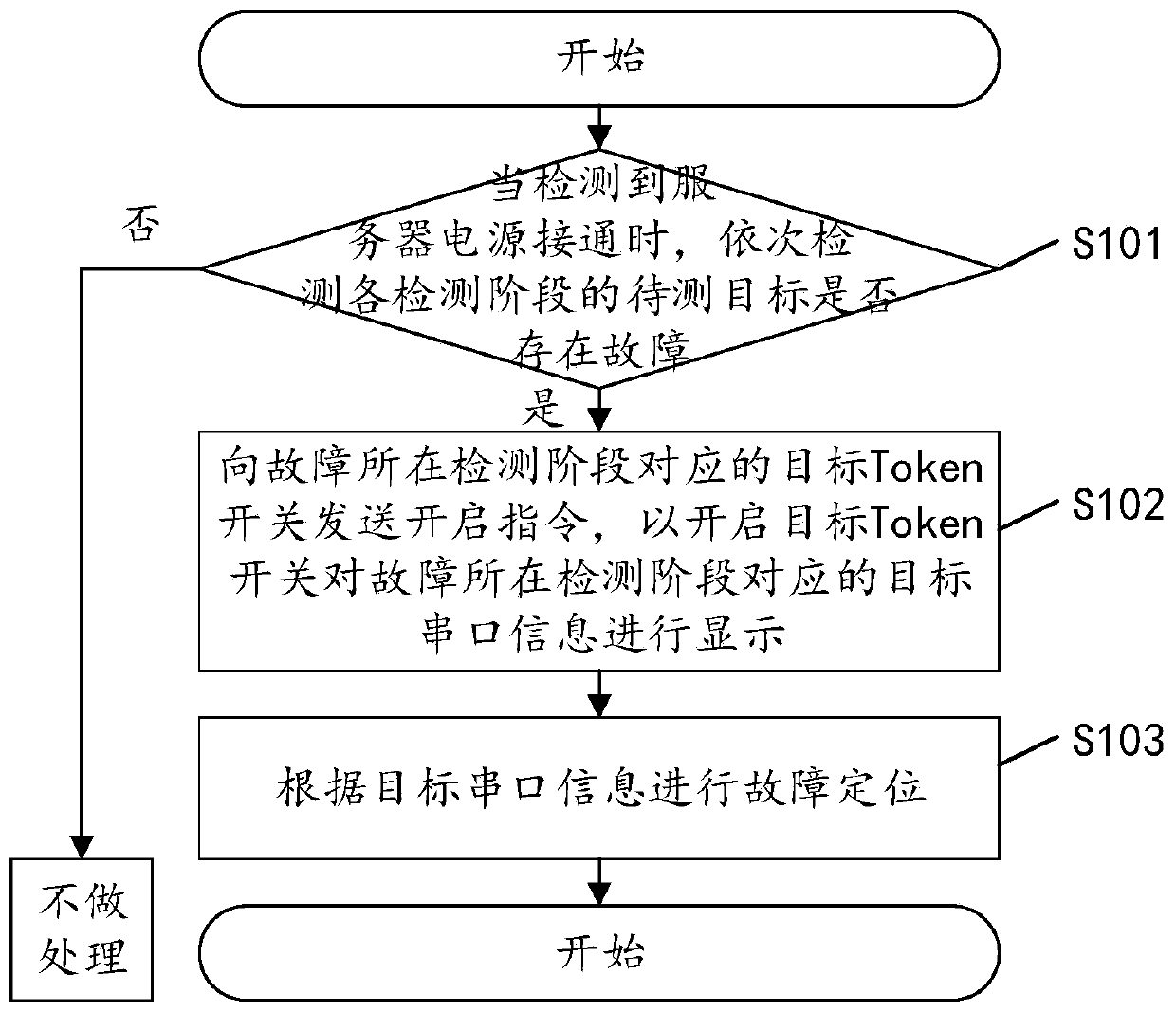
[0043] see figure 1 , figure 1 It is an implementation flow chart of a fault location method in the server startup process in the embodiment of the present invention, and the method may include the following steps:

[0044] S101: When it is detected that the server is powered on, sequentially detect whether there is a fault in the target to be tested in each detection stage, if yes, perform step S102, if not, do not process.

[0045] After the server is powered on, the input and output system will check each device inside the server. The entire power-on self-test process can be divided into stages in advance, and can be divided into multiple detection stages, for example, it can be divided into CPU detection stage, memory memory detection stage, and so on. When it is detected that the server is powered on, it is possible to sequentially detect whether there is a fault in the target to be tested in each detection stage. For example, it can be judged whether there is a fault ...

Embodiment 2

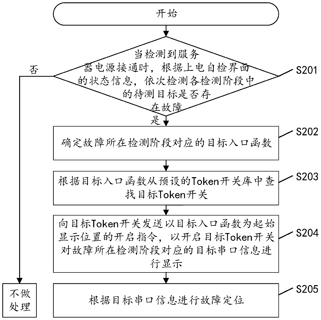
[0054] see figure 2 , figure 2 It is another implementation flowchart of the fault location method in the server startup process in the embodiment of the present invention, and the method may include the following steps:

[0055] S201: When it is detected that the server is powered on, according to the status information on the power-on self-test interface, sequentially detect whether there is a fault in the target to be tested in each detection stage, if yes, perform step S202, if not, do not process.

[0056] During the staged self-inspection, the identification information of the current inspection stage can be displayed synchronously through the power-on self-inspection interface, and according to the change of the inspection stage, the power-on self-inspection interface will be replaced with the identification information of the corresponding inspection stage. Therefore, it can be judged whether there is a fault of the target to be tested according to the status inform...


PUM


Abstract

The invention discloses a fault positioning method for a server startup process, and the method comprises the following steps: sequentially detecting whether a to-be-detected target in each detectionstage has a fault or not when a power supply of a server is detected to be switched on; if so, sending an opening instruction to a target Token switch corresponding to the detection stage of the faultso as to open the target Token switch to display target serial port information corresponding to the detection stage of the fault; and performing fault positioning according to the target serial portinformation. By applying the technical scheme provided by the embodiment of the invention, the export duration of the serial port information is greatly shortened, the fault positioning speed is increased, and the startup time is greatly shortened. The invention further discloses a fault positioning device and apparatus for the server startup process and a storage medium, and the fault positioning device and apparatus have corresponding technical effects.

Description

technical field [0001] The present invention relates to the field of computer application technology, in particular to a fault location method, device, equipment and computer-readable storage medium for a server startup process. Background technique [0002] After the server is powered on, based on the input and output system BIOS (Basic Input Output System), there will be a process of checking each internal device. to complete. The complete power-on self-test process will include CPU, basic memory, extended memory, ROM (Read Only Memory), motherboard, Complementary Metal Oxide Semiconductor CMOS (Complementary Metal Oxide Semiconductor) memory, serial and parallel ports, display card, Soft disk subsystem and keyboard test. When a problem occurs during the power-on self-inspection stage and the machine cannot be turned on, the system based on the input and output will give a prompt message or whistle a warning, and further locate the fault. [0003] The most commonly used...

Claims


Application Information

Patent Timeline
Patent Type & Authority Applications(China)
IPC IPC(8): G06F11/22G06F11/32
CPCG06F11/221G06F11/2273G06F11/327G06F11/2284
Inventor 程聪聪
Owner INSPUR SUZHOU INTELLIGENT TECH CO LTD
Learn More