
Microfilm photographing method, electronic device, system and storage medium

A technology of microfilm and electronic equipment, which is applied in the fields of instruments, optics, photography, etc., can solve the problems of inability to meet the requirements of large batches of microfilms, automatic continuous scanning, laborious, and inability to realize automatic scanning of microfilms in batches, and achieve automatic photography and reduce The amount of labor and the effect of avoiding missed shots

Active Publication Date: 2021-06-18
忆备缩微科技(北京)有限公司
View PDF5 Cites 0 Cited by
  • Summary
  • Abstract
  • Description
  • Claims
  • Application Information

AI Technical Summary

Problems solved by technology

Microfilm readers and scanners widely used at present are still unable to automatically scan microfilms in batches, especially in the case of different image sizes on the same film, and can only rely on users to manually control the microfilms to rotate clockwise or counterclockwise
Usually, a reel of 16mm microfilm has about 1200-2500 frames, and a reel of 35mm microfilm has about 600 frames. Due to the large number of frames, it is very difficult to manually shake the handle of the microfilm roll. Laborious, unable to meet the needs of large-volume, automatic and continuous scanning of microfilm

Method used


Image

  • Microfilm photographing method, electronic device, system and storage medium
  • Microfilm photographing method, electronic device, system and storage medium
  • Microfilm photographing method, electronic device, system and storage medium

Examples


Embodiment Construction

[0038] In order to better understand the above purpose, features and advantages of the present application, the solution of the present application will be further described below. It should be noted that, in the case of no conflict, the embodiments of the present application and the features in the embodiments can be combined with each other.

[0039] In the following description, a lot of specific details have been set forth in order to fully understand the present application, but the present application can also be implemented in other ways different from those described here; obviously, the embodiments in the description are only a part of the present application, and Not all examples.

[0040] The microfilm photographing solution provided in the embodiment of the present application can be applied to the continuous shooting of microfilm, that is, to restore the miniaturized image on the microfilm to an electronic image for easy reference, retrieval, and transmission; it ...


PUM


Abstract

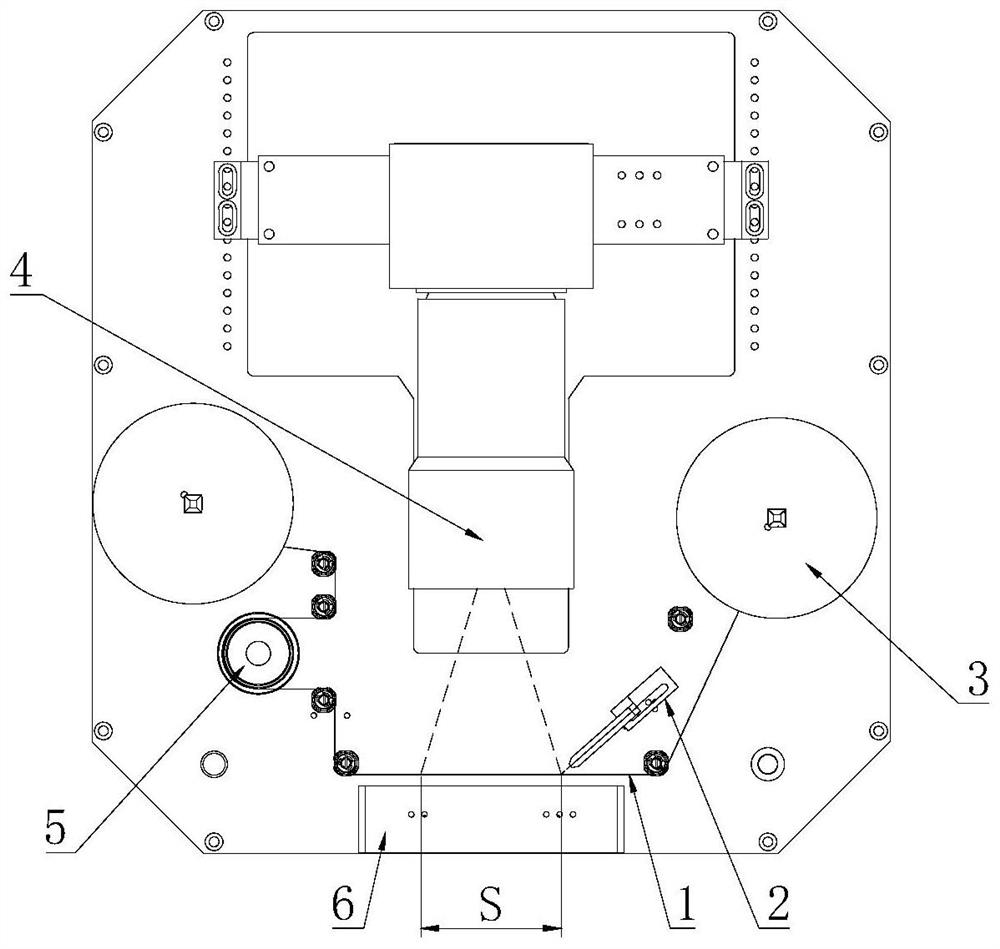
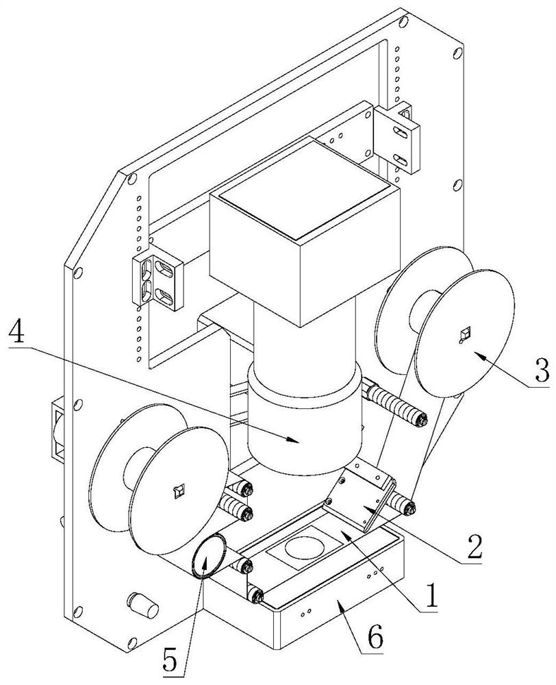
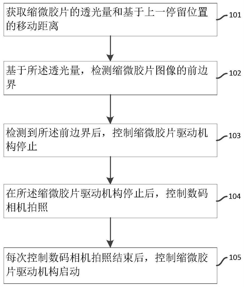
The present application relates to a microfilm photographing method, electronic equipment, system and storage medium, wherein the method includes: obtaining the light transmission amount of the microfilm and the moving distance based on the previous stop position; based on the light transmission amount and / or the moving distance, controlling The microfilm driving mechanism stops; after the microfilm driving mechanism stops, the digital camera is controlled to take pictures. The present application can determine whether the front boundary or the rear boundary of the microfilm image has reached the detection position by obtaining the light transmission amount of the microfilm; by obtaining the number of turns of the meter wheel, the distance that the microfilm moves relative to the previous stop position can be determined; For relatively long microfilm images, it is impossible to take photos at one time. The next photo position can be determined by the number of turns of the meter wheel, so as to realize continuous and automatic photo taking of the whole roll of microfilm, effectively reducing the labor load and improving the photo taking efficiency. , to meet the needs of large batches of microfilm photography.

Description

technical field [0001] The present application relates to the technical field of microfilm photographing, and in particular to a microfilm photographing method, electronic equipment, a system and a storage medium. Background technique [0002] Digital microfilm technology is to record electronic information on microfilm in the form of images. It is a carrier that uses the chemical properties of film to record electronic information. It can record a large amount of electronic data information and is suitable for permanent preservation. The microfilm recorded by digital microfilm technology has a high shrinkage rate and a large amount of information. With a traditional film reader, it is impossible to directly view the detailed content. Microfilm scanning technology or ultra-high-resolution digital camera shooting technology is required to scan the microfilm. The film image is captured as an electronic image, which can be checked in real time on the monitor after the image is ...

Claims


Application Information

Patent Timeline
Patent Type & Authority Patents(China)
IPC IPC(8): G03B15/02G03B15/00
CPCG03B15/02G03B15/00
Inventor 靳张铝毛亚雄孟祥亮王晶鑫
Owner 忆备缩微科技(北京)有限公司
Learn More