Lubricating oil viscosity detecting device

A detection device and lubricating oil technology, which is applied to measuring devices, flow characteristics, instruments, etc., can solve the problems of inability to offset impact force, inconvenient detection of lubricating oil viscosity, inability to detect lubricating oil viscosity, etc., and achieve accurate and effective detection results. Effect

Inactive Publication Date: 2019-10-25
山东腾翔产品质量检测有限公司
View PDF9 Cites 10 Cited by
  • Summary
  • Abstract
  • Description
  • Claims
  • Application Information

AI Technical Summary

Problems solved by technology

[0002] Lubricating oil mainly plays the role of lubrication, cooling, rust prevention, cleaning, sealing and buffering. It is used in various types of automobiles and mechanical equipment to reduce friction and protect machinery and processed parts. Liquid or semi-solid lubricants, so its viscosity It is especially important in the process of use. Viscosity detection needs to be carried out in the production process. The existing viscosity detection device cannot be equipped with a multi-layer shock-absorbing buffer mechanism inside, and the impact force generated by the vibration cannot be offset, and the impact of the vibration cannot be avoided. The detection has an impact, it is not convenient to detect the viscosity of lubricating oil under different temperature environments, it cannot make it possible to detect the viscosity of lubricating oil from multiple angles, and it cannot make the detection results more accurate and effective

Method used


Image

  • Lubricating oil viscosity detecting device
  • Lubricating oil viscosity detecting device
  • Lubricating oil viscosity detecting device

Examples


Embodiment Construction

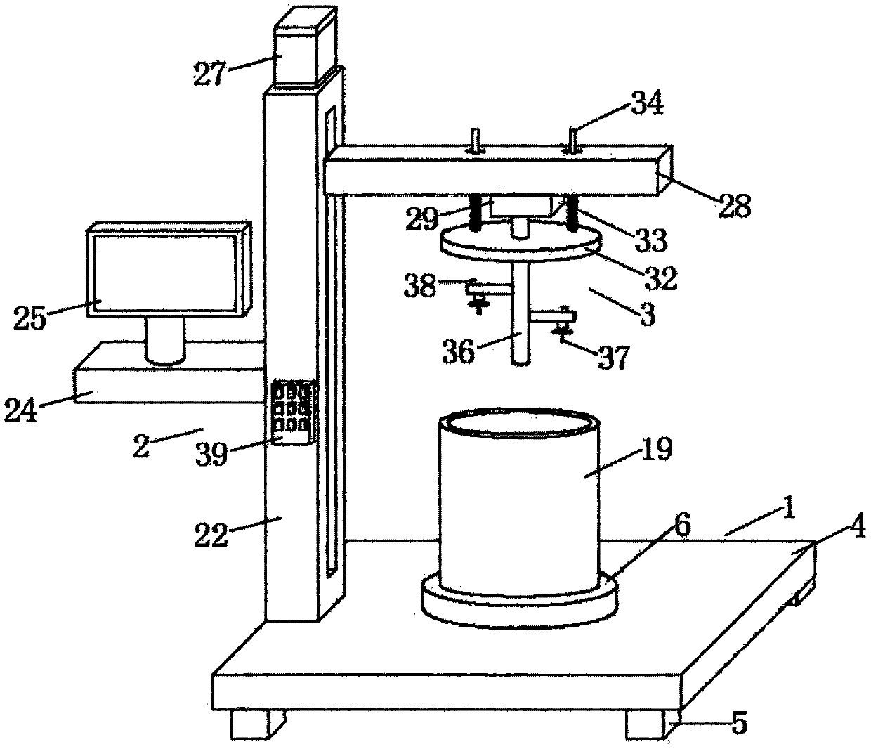
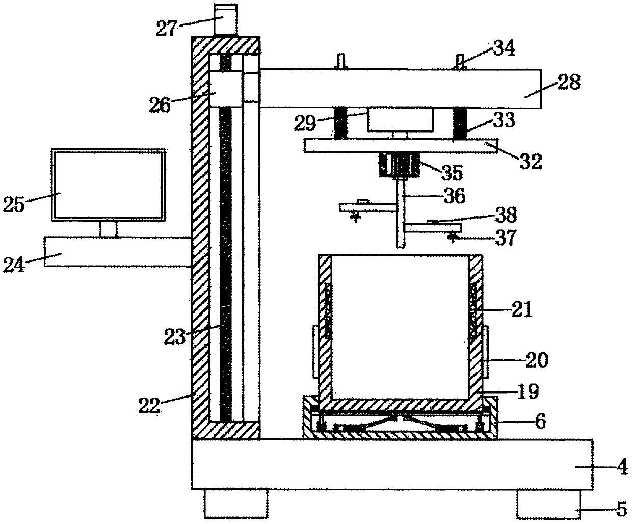
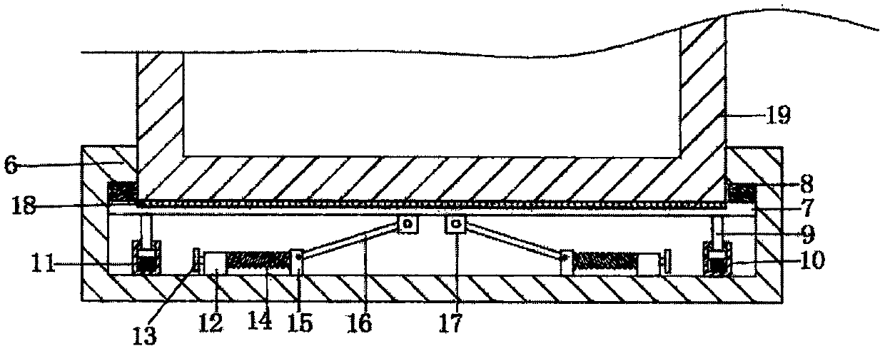
[0020] Such as Figure 1-4 As shown, this specific embodiment adopts the following technical solutions: a lubricating oil viscosity detection device, including a placement mechanism 1, an adjustment mechanism 2 and a detection mechanism 3, an adjustment mechanism 2 is installed at one end of the top of the placement mechanism 1, and the adjustment One side of the mechanism 2 is fixedly equipped with a detection mechanism 3, and the placement mechanism 1 is composed of a support base plate 4, a support foot 5, a buffer groove 6, a buffer support plate 7, a buffer spring 8, a buffer rod 9, a shock absorber groove 10, a shock absorber Spring 11, fixed block 12, unloading slide rod 13, unloading spring 14, push slide block 15, transmission rod 16, connecting block 17, rubber pad 18, material barrel 19, semiconductor refrigeration sheet 20 and electric heating plate 21 are composed, The central position of the top of the support base plate 4 is fixedly equipped with a buffer groove...


PUM


Abstract

The invention discloses a lubricating oil viscosity detecting device. The device comprises a placing mechanism, an adjusting mechanism and a detection mechanism. The adjusting mechanism is installed at one end of a top of the placing mechanism, and the detection mechanism is fixedly installed on one side of the adjusting mechanism. The placing mechanism consists of a supporting bottom plate, a supporting leg, a buffer groove, a buffer supporting plate, a buffer spring, a buffer rod, a damping groove, a damping spring, a fixing block, a unloading force slide rod, an unloading force spring, a pushing slide block, a transmission rod, a connection block, a rubber pad, a material barrel, a semiconductor refrigeration sheet and an electric heating plate. A multi-layer damping buffer mechanism isarranged in the placing mechanism, and an impact force generated by concussion is offset through the damping mechanism so as to prevent the concussion from affecting detection. Through setting the semiconductor refrigeration sheet and the electric heating plate, lubricating oil viscosity can be conveniently detected under different temperature environments, and through a pressure sensor and a viscometer, the lubricating oil viscosity can be detected from multi-azimuth angles. A detection result is accurate and effective.

Description

Technical field: [0001] The invention belongs to the technical field of detection equipment, in particular to a lubricating oil viscosity detection device. Background technique: [0002] Lubricating oil mainly plays the role of lubrication, cooling, rust prevention, cleaning, sealing and buffering. It is used in various types of automobiles and mechanical equipment to reduce friction and protect machinery and processed parts. Liquid or semi-solid lubricants, so its viscosity It is especially important in the process of use. Viscosity detection needs to be carried out in the production process. The existing viscosity detection device cannot be equipped with a multi-layer shock-absorbing buffer mechanism inside, and the impact force generated by the vibration cannot be offset, and the impact of the vibration cannot be avoided. The detection has an impact, it is not convenient to detect the viscosity of lubricating oil under different temperature environments, it cannot make it...

Claims


Application Information

Patent Timeline
Patent Type & Authority Applications(China)
IPC IPC(8): G01N11/16F16F15/04F16F15/02
CPCF16F15/02F16F15/04G01N11/00G01N11/162G01N2011/002
Inventor 胡艳娣宋淑霞邵玉洁陈姝
Owner 山东腾翔产品质量检测有限公司
Why Eureka
Try Eureka