Rotor sealing structure of internal mixer

A technology of rotor sealing and internal mixer, which is applied in the field of mechanical equipment sealing, can solve the problems of large influence of external factors and material leakage, etc., and achieve the effect of improving sealing effect, ensuring quality and realizing zero leakage

Inactive Publication Date: 2019-10-25
QINGDAO UNIV OF SCI & TECH
View PDF20 Cites 0 Cited by
  • Summary
  • Abstract
  • Description
  • Claims
  • Application Information

AI Technical Summary

Problems solved by technology

There are two disadvantages in the traditional internal mixer rotor sealing device: one is that they are all located outside the mixing chamber; the other is that they are greatly affected by external factors. material leakage

Method used


Image

  • Rotor sealing structure of internal mixer
  • Rotor sealing structure of internal mixer
  • Rotor sealing structure of internal mixer

Examples


Embodiment 1

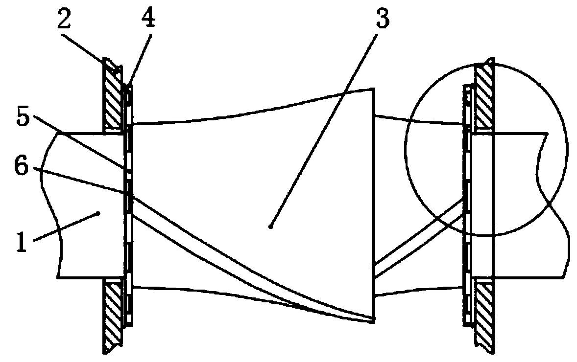
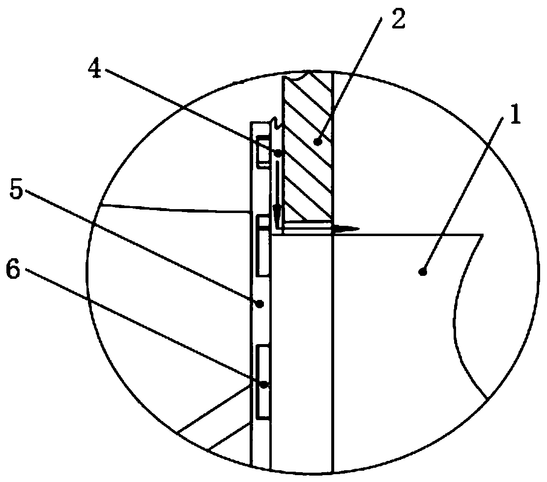
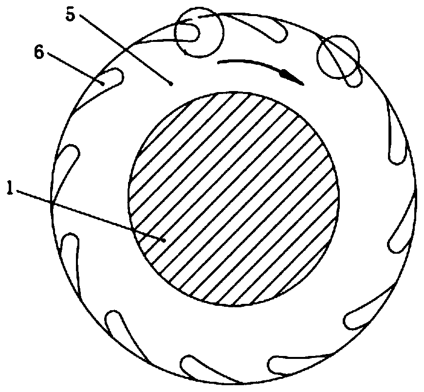
[0023] The main structure of the internal mixer rotor sealing structure involved in this embodiment includes a rotor shaft 1, a side wall 2, a rotor 3, a gap 4, a rotor working end face 5 and a spiral groove 6; both ends of the rotor shaft 1 protrude from the side wall 2, A rotor 3 is arranged on the rotor shaft 1 between the side walls 2 , there is a gap 4 between the side walls 2 and the rotor 3 , the end of the rotor 3 is provided with a rotor working end surface 5 , and a spiral groove 6 is opened on the rotor working end surface 5 .

[0024] The number of spiral grooves 6 involved in this embodiment is 12, which are equally spaced on the working end surface 5 of the rotor, which can effectively balance the radial force on the rotor 3. When the number of spiral grooves 6 is less than 12, the spiral grooves 6 The conveying volume of materials is small, and the sealing effect is not obvious. When the number of spiral grooves 6 is more than 22, the adjacent spiral grooves 6 ar...


PUM


Abstract

The invention belongs to the technical field of mechanical equipment sealing, and particularly relates to a rotor sealing structure of an internal mixer. The main structure of the rotor sealing structure comprises a rotor shaft, a side wall, a rotor, a gap, a rotor working end face and a spiral groove. The spiral sealing principle is applied to the gap sealing between the rotor working end face and the side wall of a mixing chamber, and materials in the gap is conveyed back to the mixing chamber through a spiral groove on the rotor working end face, so that the leakage of the materials is prevented; and the sealing of high-viscosity polymer melt materials is carried out, and specifically the spiral groove is processed on the rotor working end face, wherein the rotation direction of the spiral groove is opposite to the rotation direction of the rotor shaft. When the rotor working end face rotates clockwise, the rotation direction of the spiral groove is anticlockwise; when the rotor working end face rotates anticlockwise, the rotation direction of the spiral groove is clockwise, the spiral groove drives the materials to move, a pumping effect is generated, and the materials are conveyed back to the mixing chamber; and when the materials conveyed by the spiral groove and the materials leaked from the gap are balanced, the dynamic sealing is realized.

Description

Technical field: [0001] The invention belongs to the technical field of mechanical equipment sealing, and specifically relates to a rotor sealing structure of an internal mixer, which introduces a spiral groove seal into the rotor seal in a mixing chamber, and realizes the sealing of rubber material from the source through the pumping action of the spiral groove. Background technique: [0002] The internal mixer is the key equipment for rubber mixing production. In the process from raw material (raw rubber) to finished product, mixing is the first process, which plays an extremely important role and is the most critical step in rubber modification. Whether the mixing is uniform or not determines the effect of the subsequent process, and affects the product performance and service life to a large extent. In all rubber (plastic) product industries, the internal mixer is an important production equipment, whether it can work safely, normally and smoothly directly affects whethe...

Claims


Application Information

Patent Timeline
Patent Type & Authority Applications(China)
IPC IPC(8): B29B7/14
CPCB29B7/14B29B7/183B29B7/186
Inventor 林广义刘彦昌于芳于博全刘守一梁振宁梁栋胡亚菲
Owner QINGDAO UNIV OF SCI & TECH
Why Eureka
Try Eureka