
Polishing method and device of circular arc surface of connecting rod

An arc surface and connecting rod technology, applied in grinding/polishing equipment, grinding machines, manufacturing tools, etc., can solve the problems of difficult to guarantee polishing accuracy, difficult grinding and polishing, and bulky products, and achieve reliable position, simple method, low cost effect

Active Publication Date: 2019-10-25
荆州环球汽车零部件制造有限公司
View PDF7 Cites 1 Cited by
  • Summary
  • Abstract
  • Description
  • Claims
  • Application Information

AI Technical Summary

Problems solved by technology

The existing polishing method is to add fixtures on the milling machine, clamp the connecting rod on the milling machine, and perform polishing by rotating the workpiece of the connecting rod. Because the product itself is relatively heavy, and the rotation and polishing are controlled manually, the operation is time-consuming Laborious, and the polishing accuracy is difficult to guarantee
Moreover, the surface to be polished of this special connecting rod workpiece is not a complete cylindrical surface, but an arc surface with an included angle of about 200°. Since the included angle exceeds 180°, some of the arc surface to be polished is located at the big end of the connecting rod. Below the center line, it is more difficult to grind and polish

Method used


Image

  • Polishing method and device of circular arc surface of connecting rod
  • Polishing method and device of circular arc surface of connecting rod
  • Polishing method and device of circular arc surface of connecting rod

Examples


Embodiment Construction

[0037] The present invention will be further described below in conjunction with drawings and embodiments.

[0038] The specific implementation steps of the method for polishing the circular arc surface of connecting rod of the present invention are as follows:

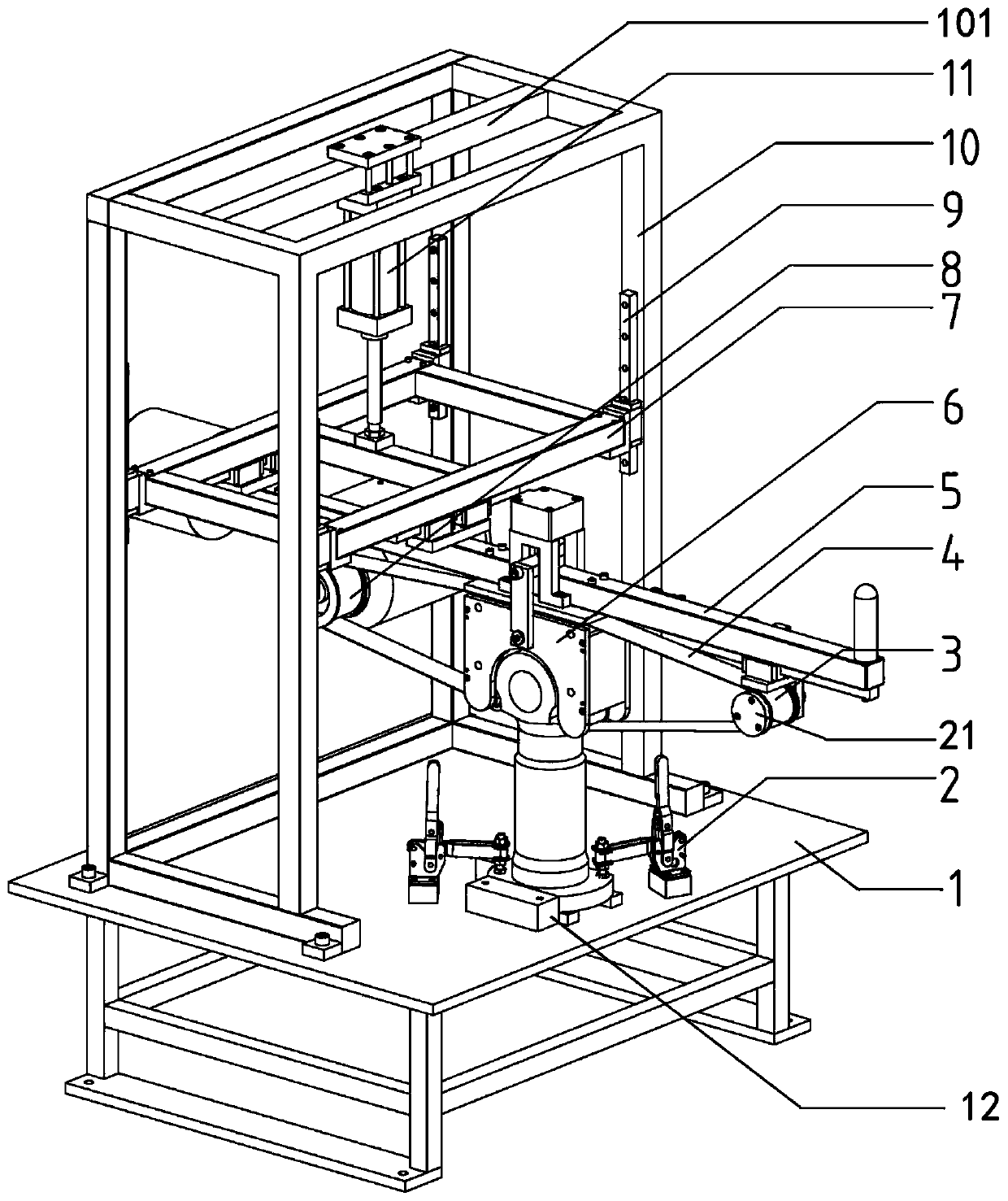
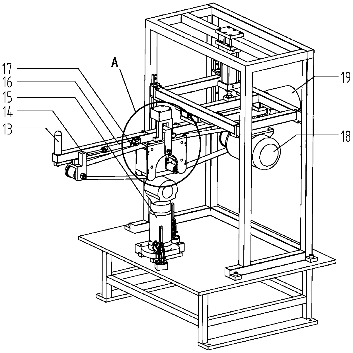
[0039] S1. Put the connecting rod 15 close to the limit block 12 of the device of the present invention, pull two quick clamps 2 to clamp the connecting rod, and place the connecting rod to be polished with the arc surface upward;

[0040] S2. Turn on the switch of the lifting cylinder 11, so that the lifting cylinder 11 drives the lifting seat 7, and drives the polishing belt operation unit to descend, so that the polishing belt 4 is positioned on the arc surface of the connecting rod;

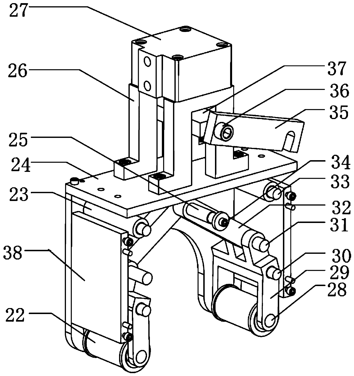
[0041]S3, start the switch of the hinge loose clamp cylinder 27, the hinge clamp cylinder 27 drives the hinge loose clamp connecting seat 37, drives the follower pin 25 to go down, and the hinge clamp 29 clamps the polishing belt 4 o...


PUM


Abstract

The invention provides a polishing method and device of a circular arc surface of a connecting rod. The method comprises the following steps: fixing a connecting rod workpiece, and upwards positioningthe circular arc surface, to be polished, of the connecting rod; lifting the positions of polishing belts until the polishing belts are positioned onto the circular arc surface of the connecting rod;clamping the polishing belts at two sides of the circular arc surface of the connecting rod, wherein the polishing belts are close to the whole circular arc surface, to be polished, of the connectingrod workpiece, and the polishing belts and an end point of the circular arc surface of the connecting rod workpiece are subjected to tangent relationship, so that the stress to the polishing belts and the circular arc surface of the connecting rod workpiece is consistent; and operating the polishing belts to polish the circular arc surface of the connecting rod. The device comprises a workpiece fixing unit, a lifting unit, a left and right moving unit and a polishing belt operating unit. With the adoption of the method and the device, the outer circular arc surface with an included angle of about 200 degrees of the connecting rod can be polished; in addition, the device is simple in structure, quick to assemble, convenient to use, high in processing efficiency, high in polishing accuracy,time and force saving, and wide in applicable scope; the a wide circular arc surface can be polished.

Description

technical field [0001] The invention relates to a method and a device for polishing the circular arc surface of a connecting rod, belonging to the technical field of mechanical processing. Background technique [0002] The connecting rod is a part that connects the piston and the crankshaft. Its function is to convert the reciprocating motion of the piston into the rotational motion of the crankshaft, and transmit the force acting on the piston to the crankshaft to output power. The stress situation of the connecting rod in the work is relatively complicated, which is not only affected by the alternating tensile stress and compressive stress, but also subjected to the bending stress. Because of the complex stress situation of the connecting rod, there are strict requirements for the accuracy of the connecting rod shape. [0003] The roundness and roughness of the outer surface of the arc at the big end of the connecting rod are very high. For a connecting rod currently prod...

Claims


Application Information

Patent Timeline
Patent Type & Authority Applications(China)
IPC IPC(8): B24B1/00B24B21/16B24B21/18B24B21/20
CPCB24B1/00B24B21/16B24B21/18B24B21/20
Inventor 范朝阳赵华
Owner 荆州环球汽车零部件制造有限公司
Learn More