
Control system for knee joint correction instrument

A control system and knee joint technology, applied in the direction of medical science, etc., can solve the problems of uncomfortable fixation, overcorrection, and difficulty in adjusting the fit between the fixation structure and the patient's body, so as to optimize wearing comfort and optimize treatment. effect, the effect of ensuring the safety of the device

Active Publication Date: 2019-10-25
安徽一锤通物联科技股份有限公司
View PDF16 Cites 0 Cited by
  • Summary
  • Abstract
  • Description
  • Claims
  • Application Information

AI Technical Summary

Problems solved by technology

[0003] During the treatment, the first choice is to shovel and relax the tense muscles. If there is tension on one side or one direction of the two ligaments, the surgeon uses the knee joint instrument to block the patient's patella and rotate the handle to make the knee joint instrument work hard. Hold the patella back and forth repeatedly to the opposite side of the tension, and then rotate left and right until it is completely released. After the patella is reset, you can use the fascia to release it at the popliteal fossa, Chengshan points, quadriceps femoris, and gastrocnemius The hammer should be released to consolidate the curative effect of patella reduction, and then it must be clear which meridian is blocked and dredged, so as to achieve the purpose of treating the free movement of the knee joint. This requires knee joint correction equipment to correct the knee joint, and the knee joint During the use of orthodontic devices, it is difficult to control the strength of the driving structure for correction, and it is also difficult to adjust the extrusion fit between the fixed structure and the patient's body. The present invention proposes a control system of a knee joint correction device to solve the problems existing in the prior art

Method used


Image

  • Control system for knee joint correction instrument

Examples


Embodiment Construction

[0016] In order to deepen the understanding of the present invention, the present invention will be further described below in conjunction with the examples, which are only used to explain the present invention, and do not constitute a limitation to the protection scope of the present invention.

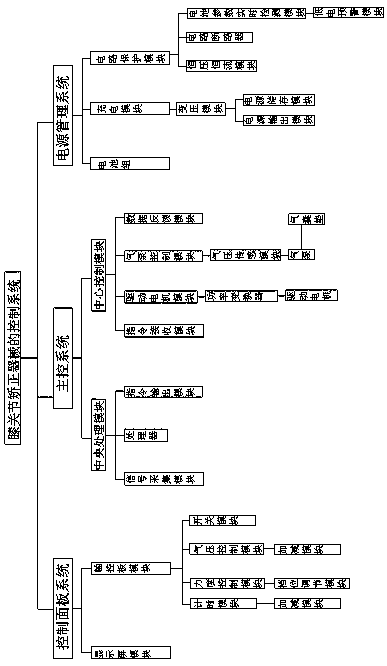
[0017] according to figure 1 As shown, this embodiment proposes a control system for a knee joint correction device, including a main control system, a control panel system, and a power management system. The power management system is electrically connected to the control panel system and the main control system, respectively. The control panel system is electrically connected to the main control system, the main control system includes a central processing module and a central control module, the central processing module includes a signal acquisition module, a processor and an instruction output module, and the central control module includes an instruction receiving module module...


PUM


Abstract

The invention provides a control system for a knee joint correction instrument. The control system comprises a main control system, a control panel system and a power management system, wherein the power management system is electrically connected with the control panel system and the main control system separately, the control panel system is electrically connected with the main control system, and the main control system comprises a central processing module and a central control module. The control system for the knee joint correction instrument has the advantages that by controlling a force control module, a command can be sent to make a driving motor control module change the power of a driving motor, thereby adjusting the correction force of a driving structure in the knee joint correction instrument, and feeding back force data on a display module in real time; by controlling an air pressure control module, a command can be sent to make an air pump adjust the air pressure of anairbag cushion, thereby adjusting the pressing degree of a fixing structure in the knee joint correcting instrument, and feeding back air pressure data on the display module in real time. In conclusion, convenience is provided for adjusting the correcting force and fitting degree according to actual situations of a patient, that is, not only is the treatment effect optimized, but also the wearingcomfort is optimized.

Description

technical field [0001] The invention relates to the technical field of control systems, in particular to a control system of a knee joint correction device. Background technique [0002] Knee arthropathy is mostly due to the change and imbalance of the tensile stress of the quadriceps, sartorius, and medial and lateral collateral ligaments; the unbalanced tensile stress of the patellar ligament; the displacement of the patella and the upper and lower three bone axes in different directions; the inability to return to normal physiology The position of this shift is corrected by the rotation of the knee joint device, so that the muscles and ligaments with tensile stress are balanced, the patella returns to its original position, and the motor function reaches normal. This displacement of the patella is called functional displacement; [0003] During the treatment, the first choice is to shovel and relax the tense muscles. If there is tension on one side or one direction of th...

Claims


Application Information

Patent Timeline
Patent Type & Authority Applications(China)
IPC IPC(8): A61F5/01
CPCA61F5/0123
Inventor 王世峰鮑应泽
Owner 安徽一锤通物联科技股份有限公司
Learn More