
Assembly process of rotor and end cover in brushless motor and assembly equipment

A technology of brushless motor and assembly process, which is applied in electromechanical devices, manufacturing motor generators, manufacturing stator/rotor bodies, etc., can solve the problems of poor motor performance consistency, uncontrollable installation size, and rotor up and down movement. Achieve the effect of good assembly effect, precise control of installation size, and reduction of movement clearance

Pending Publication Date: 2019-10-22
江西沃德尔科技有限公司
View PDF0 Cites 0 Cited by
  • Summary
  • Abstract
  • Description
  • Claims
  • Application Information

AI Technical Summary

Problems solved by technology

[0003] The invention provides a rotor and an end cover in a brushless motor that can prevent the rotor from moving up and down and precisely control the installation size, thereby effectively ensuring the stability of the brushless motor, good consistency in motor performance, and small variation. Assembly process and assembly equipment; it solves the problem that the rotor of the brushless motor in the prior art moves up and down during the assembly process, and the installation size is uncontrollable, which leads to poor consistency, poor stability, and large variation of the motor performance technical issues

Method used


Image

  • Assembly process of rotor and end cover in brushless motor and assembly equipment
  • Assembly process of rotor and end cover in brushless motor and assembly equipment
  • Assembly process of rotor and end cover in brushless motor and assembly equipment

Examples


Embodiment

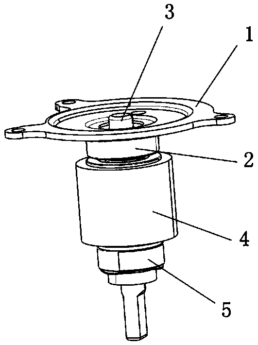
[0033] like figure 1 As shown, the rotor assembly in the brushless motor includes a rotor shaft 3, a rotor magnetic ring 4 is sleeved in the middle of the rotor shaft 3, a lower bearing 5 is sleeved under the rotor magnetic ring 4, and the upper end of the rotor shaft 3 is an end cover Component 9.

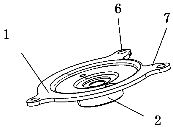
[0034] like figure 2 As shown, the end cover assembly in the brushless motor includes an end cover 1 , and an upper bearing 2 is installed in the center of the end cover 1 . The outer circumferential surface of the end cover 1 is integrally formed with three lugs 7 , and the lugs 7 are provided with positioning holes 6 .

[0035] The assembly process for assembling the end cap assembly to the rotor is as follows:

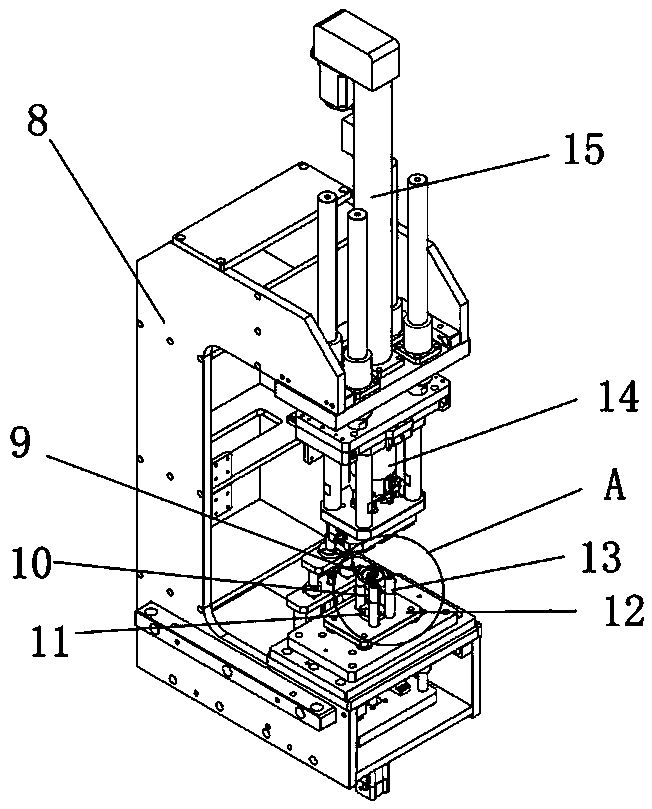
[0036] In the first step, the rotor 10 is placed on the lower mold 12, the rotor shaft 3 is placed in the positioning hole in the lower mold, the three uprights 13 around the positioning hole are lifted, and the end cap assembly 9 is placed on the upright post 13. ...


PUM


Abstract

The invention relates to an assembly process and equipment, and specifically relates to an assembly process of a rotor and an end cover in a brushless motor and assembly equipment. The assembly equipment comprises a rack, wherein the rack is equipped with an upper die and a lower die, the upper die is connected with a servo press, and the lower die is equipped with a vertical column. The assemblyprocess comprises the steps of placing the rotor on the lower die, and placing an end cover assembly on the vertical column; and positioning by taking the upper and lower surfaces of the inner ring ofan upper bearing in the end cover assembly as reference surfaces, and then pressing. The invention provides an assembly process of the rotor and the end cover in the brushless motor and the assemblyequipment, which can prevent the rotor from moving up and down, can accurately control the installation size, thus effectively ensures the stability of the brushless motor, and has good consistency ofthe motor performance and small variation; and the technical problems that the rotor of the brushless motor in the prior art moves up and down, the installation size cannot be controlled, and thus the motor is caused to be poor in consistency, poor in stability and great in variation are solved.

Description

technical field [0001] The invention relates to an assembling process and equipment thereof, in particular to an assembling process and assembling equipment of a rotor and an end cover in a brushless motor. Background technique [0002] In modern society, brushless motors have been widely used, and brushless motors are basically composed of a housing, a stator assembly and a rotor assembly. Install the stator assembly within the housing, and then mate the rotor assembly with the stator assembly. During the assembly process, the installation of various components will affect the performance of the final brushless motor. However, in the current installation process, in the current industry, the dimensional tolerance of the end cover assembly to the rotor assembly is large, the degree of freedom is large, and the rotor moves up and down the gap is large. The above problems will eventually lead to the performance of the brushless motor. Poor sex, big variation, etc. SUMMARY ...

Claims


Application Information

Patent Timeline
IPC IPC(8): H02K15/02H02K15/14
CPCH02K15/02H02K15/14
Inventor 杨定兵曹彦湖全伟
Owner 江西沃德尔科技有限公司
Learn More