
Mechanism for limiting and releasing clamp

A clamp and limit seat technology, which is applied in the field of clamp limit and release limit mechanism, can solve the problems of clamp, battery mass, gap size is not fixed, electrolyte spilled, etc., to facilitate the next transfer, Effect of constant gap size and reduced installation space

Pending Publication Date: 2019-10-22
SHENZHEN DIRUIDA AUTOMATION
View PDF0 Cites 0 Cited by
  • Summary
  • Abstract
  • Description
  • Claims
  • Application Information

AI Technical Summary

Problems solved by technology

[0002] In the electrolyte injection process of the battery, it is necessary to transfer the position of the jig containing the battery. During the transfer process, due to the parallel extrusion of multiple jigs and the large mass of the jig and the battery, the inertia generated at the end of the movement will make the most A clamp at the front end collides violently with the limit mechanism, causing electrolyte spillage, damage to the clamp, excessive noise, and the squeezed clamp will be stuck during the next reversing transfer
[0003] In the transfer of general fixtures, a set of mechanisms composed of one cylinder or a combination of cylinders is usually installed at the front limit position to reverse push and limit the fixture. However, due to the large number of fixtures and batteries and the large inertia, the required reverse cylinder It will also increase, resulting in inaccurate limit positions. After the limit is released, the size of the gap is not fixed, which will affect the re-transfer of the fixture. Due to the influence of other mechanism positions, the space is limited

Method used


Image

  • Mechanism for limiting and releasing clamp
  • Mechanism for limiting and releasing clamp
  • Mechanism for limiting and releasing clamp

Examples


Embodiment Construction

[0017] The following will clearly and completely describe the technical solutions in the embodiments of the present invention with reference to the accompanying drawings in the embodiments of the present invention. Obviously, the described embodiments are only some, not all, embodiments of the present invention. Based on the embodiments of the present invention, all other embodiments obtained by persons of ordinary skill in the art without making creative efforts belong to the protection scope of the present invention.

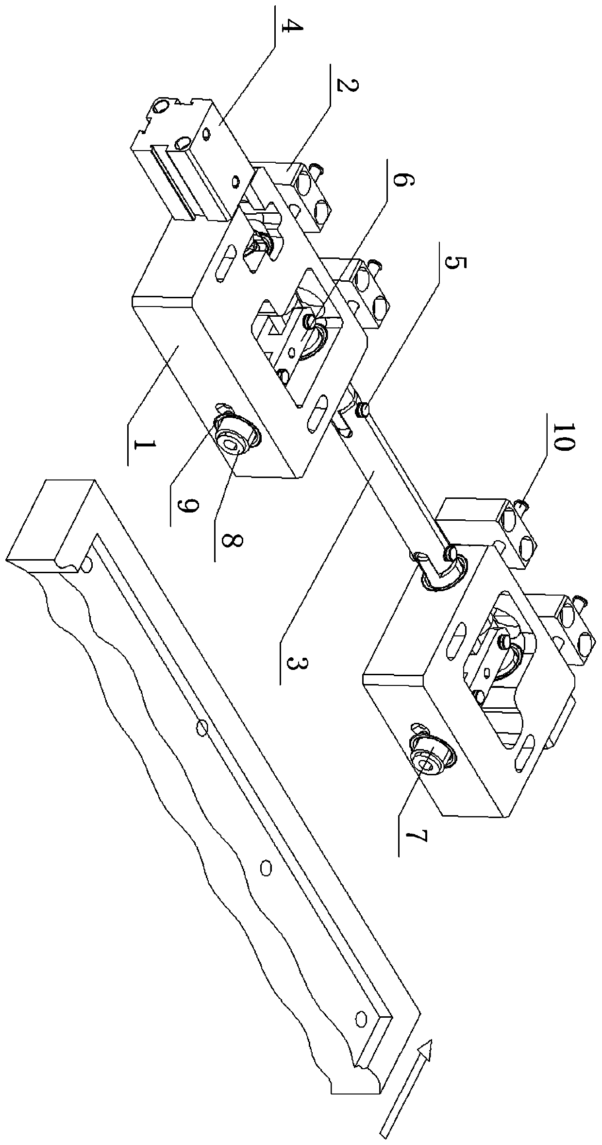
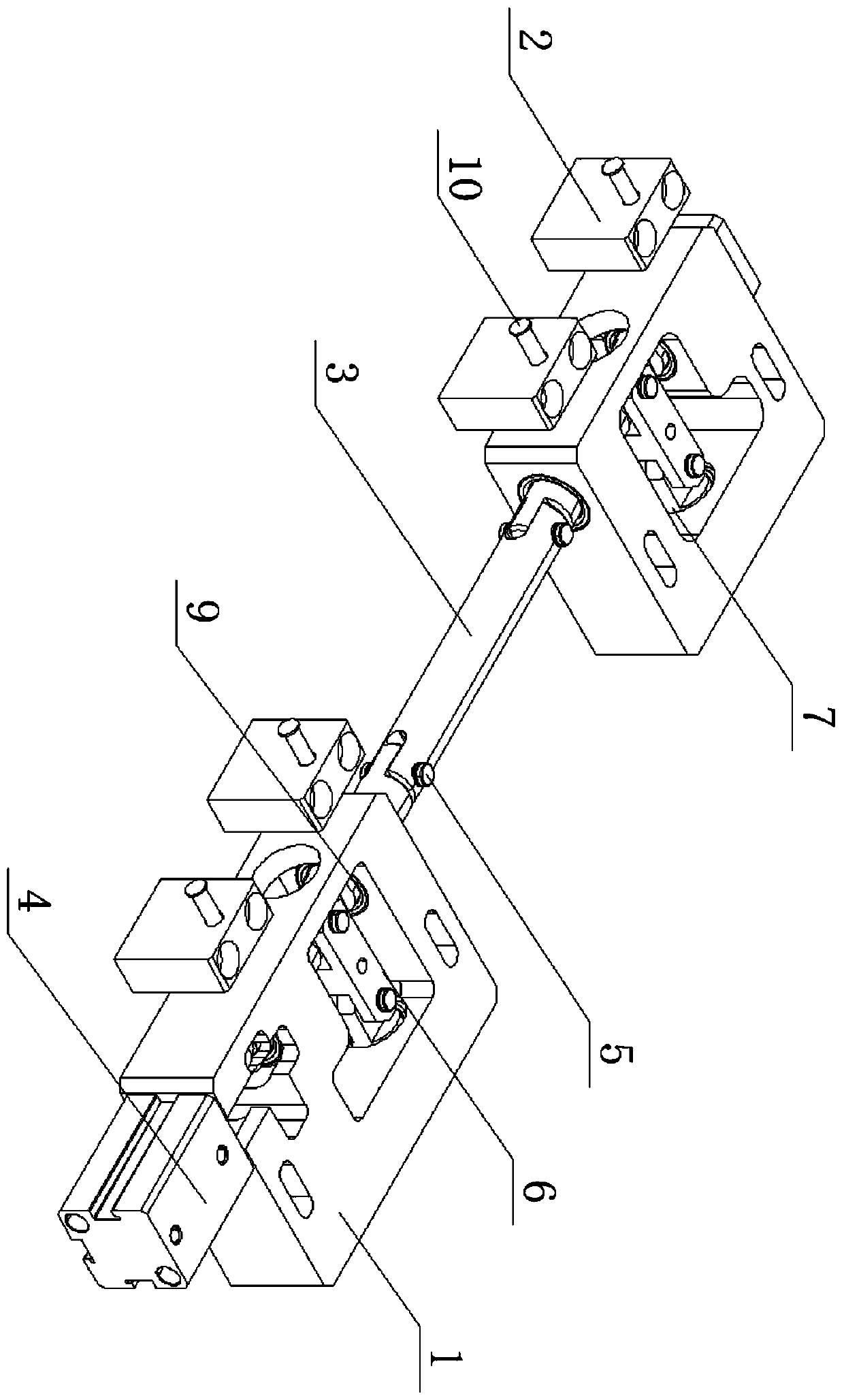
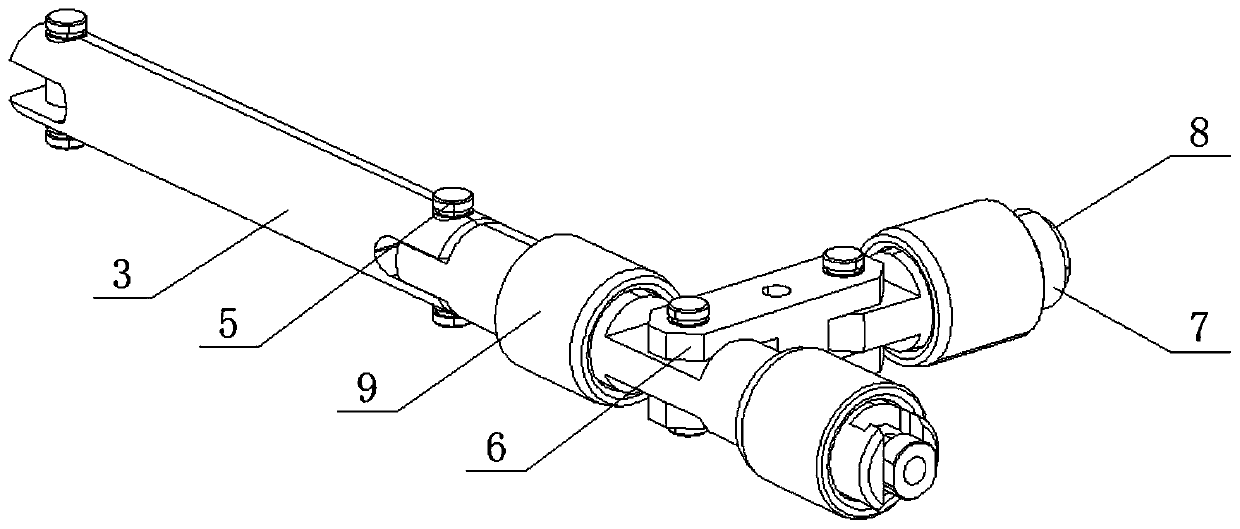
[0018] see Figure 1-5 , a mechanism for limiting and releasing the position of the clamp, including a battery clamp and a fixing seat 1 placed on one side of the battery clamp. One side of the fixture is correspondingly fixed with a group of limit seats 2, and the limit seats 2 are connected with an adjusting bolt 10, and one end of the adjusting bolt 10 is movably connected with one side of the fixing seat 1 (here the connection is equivalent to the end of t...


PUM


Abstract

The invention relates to the technical field of battery production and discloses a mechanism for limiting and releasing a clamp. The mechanism comprises fixing seats placed on one side of a battery clamp; every two fixing seats form a group and are arranged on the side edge of the battery clamp; limiting seats are correspondingly mounted on one side of one corresponding fixing seat; the two groupsof fixing seats are connected and driven by a driving rod; one end of the driving rod is sleeved in the output end of an air cylinder and connected with a connecting rod; the other end of the connecting rod is connected with an ejector rod; and one end of the ejector rod extends out of the fixing seats. Through mutual stress among the driving rod, the connecting rod and the ejector rod, a stresspoint is finally transmitted to the fixing bases through the driving rod to be counteracted, and the device can bear large inertia force by changing the limiting mode. The thrust required by the air cylinder is reduced, and the model and the specification of the air cylinder do not need to be too large. The driving rod drives the connecting rod to change the angle, so the ejector rod is retracted,the stroke of the air cylinder is not changed, the gap size of the battery clamp is constant after limiting is removed, and the battery clamp can be conveniently transferred next time.

Description

technical field [0001] The invention relates to the technical field of battery production, in particular to a mechanism for limiting and releasing a clamp. Background technique [0002] In the electrolyte injection process of the battery, it is necessary to transfer the position of the jig containing the battery. During the transfer process, due to the parallel extrusion of multiple jigs and the large mass of the jig and the battery, the inertia generated at the end of the movement will make the most A clamp at the front end collides violently with the limit mechanism, causing electrolyte spillage, damage to the clamp, excessive noise, and the squeezed clamp will be stuck during the next reversing transfer. [0003] In the transfer of general fixtures, a set of mechanisms composed of one cylinder or a combination of cylinders is usually installed at the front limit position to reverse push and limit the fixture. However, due to the large number of fixtures and batteries and ...

Claims


Application Information

Patent Timeline
IPC IPC(8): H01M2/36H01M6/00H01M10/04
CPCH01M6/005H01M10/0404H01M50/60Y02P70/50
Inventor 魏家雄
Owner SHENZHEN DIRUIDA AUTOMATION
Learn More