A Fault Identification Method of mmc DC Transmission Line Based on SOD Transformation
A DC transmission line, fault identification technology, applied in the direction of fault location, fault detection according to conductor type, etc., can solve problems such as damage to the transmission system
- Summary
- Abstract
- Description
- Claims
- Application Information
AI Technical Summary
Problems solved by technology
Method used
Image
Examples
Embodiment 1
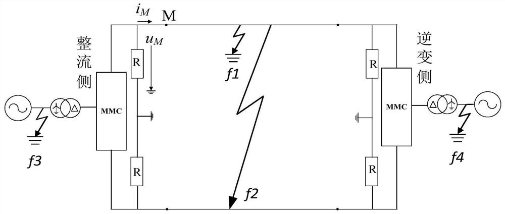
[0031] Example 1: Establish as attached figure 1 The MMC HVDC transmission system shown is used as a simulation model. The winding on the valve side of the connecting transformer adopts a delta connection without a neutral point, and the AC side of the connecting transformer adopts a star connection, and its neutral point is directly grounded. The DC side is grounded through the clamping resistor, which has a large resistance value. Its main function is to clamp the two-pole voltage and provide a potential reference point for the DC system during normal operation. The DC voltage is ±320kV, the transmission line is 400km, and M is the measurement terminal.
[0032] (1) Fault location: positive ground fault f 1 , 160km away from the measuring end; the fault start time is 0.4s; the sampling frequency is 10kHz.
[0033] (2) Acquire fault voltage and current data at the measurement point according to the first step in the manual.
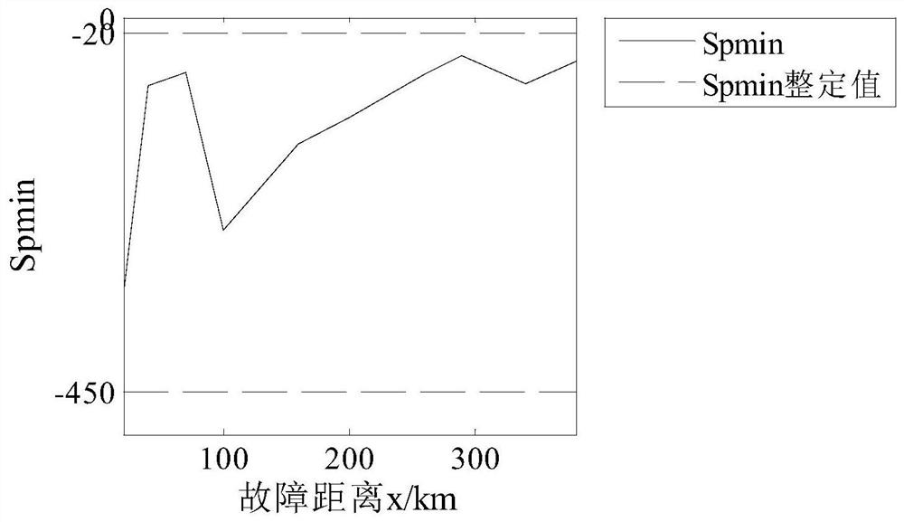
[0034] (3) Acquire the fault voltage and curre...
Embodiment 2
[0037] Example 2: Establish as attached figure 1 The MMC HVDC transmission system shown is used as a simulation model. The winding on the valve side of the connecting transformer adopts a delta connection without a neutral point, and the AC side of the connecting transformer adopts a star connection, and its neutral point is directly grounded. The DC side is grounded through the clamping resistor, which has a large resistance value. Its main function is to clamp the two-pole voltage and provide a potential reference point for the DC system during normal operation. The DC voltage is ±320kV, the transmission line is 400km, and M is the measurement terminal.
[0038] (1) Fault location: bipolar short circuit fault f 2 , 160km away from the measuring end; the fault start time is 0.4s; the sampling frequency is 10kHz.
[0039] (2) Acquire fault voltage and current data at the measurement point according to the first step in the manual.
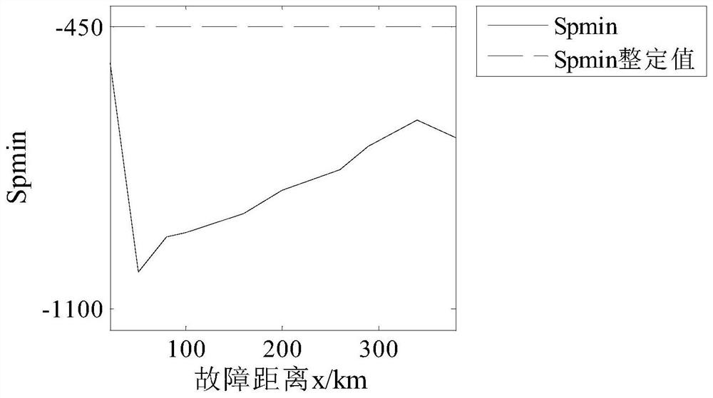
[0040] (3) Acquire the fault voltage and...
Embodiment 3
[0043] Example 3: Establish as attached figure 1 The MMC HVDC transmission system shown is used as a simulation model. The winding on the valve side of the connecting transformer adopts a delta connection without a neutral point, and the AC side of the connecting transformer adopts a star connection, and its neutral point is directly grounded. The DC side is grounded through the clamping resistor, which has a large resistance value. Its main function is to clamp the two-pole voltage and provide a potential reference point for the DC system during normal operation. The DC voltage is ±320kV, the transmission line is 400km, and M is the measurement terminal.
[0044] (1) Fault location: Three-phase short-circuit fault on the AC side of the rectifier station f3 ; The start time of the fault is 0.4s; the sampling frequency is 10kHz.
[0045] (2) Acquire fault voltage and current data at the measurement point according to the first step in the manual.
[0046] (3) Acquire the fau...
PUM
 Abstract
Description
Claims
Application Information
 - R&D
- Intellectual Property
- Life Sciences
- Materials
- Tech Scout
- Unparalleled Data Quality
- Higher Quality Content
- 60% Fewer Hallucinations
Browse by: Latest US Patents, China's latest patents, Technical Efficacy Thesaurus, Application Domain, Technology Topic, Popular Technical Reports.
© 2025 PatSnap. All rights reserved.Legal|Privacy policy|Modern Slavery Act Transparency Statement|Sitemap|About US| Contact US: help@patsnap.com


