
Push-pull rolling device for auxiliary rebar connection

A technology of rolling device and steel bar, which is applied in the field of push-pull rolling device, can solve the problems such as rotation and axial movement of semi-finished steel bar, and achieve the effect of improving mechanical installation efficiency, improving steel bar quality and finished product quality, and reducing labor intensity

Active Publication Date: 2021-04-02
CHINA FIRST METALLURGICAL GROUP
View PDF6 Cites 0 Cited by
  • Summary
  • Abstract
  • Description
  • Claims
  • Application Information

AI Technical Summary

Problems solved by technology

It can only be used for steel bar movement, and cannot solve the problem of steel bar rotation and axial movement in the production process of semi-finished products and finished products

Method used


Image

  • Push-pull rolling device for auxiliary rebar connection
  • Push-pull rolling device for auxiliary rebar connection
  • Push-pull rolling device for auxiliary rebar connection

Examples


Embodiment Construction

[0021] In order to have a clearer understanding of the technical features, purposes and effects of the present invention, the specific implementation manners of the present invention will now be described in detail with reference to the accompanying drawings.

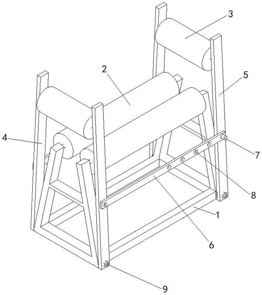
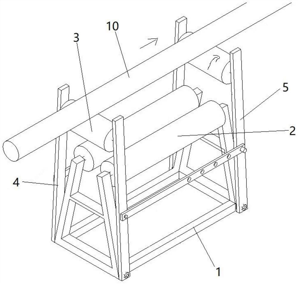
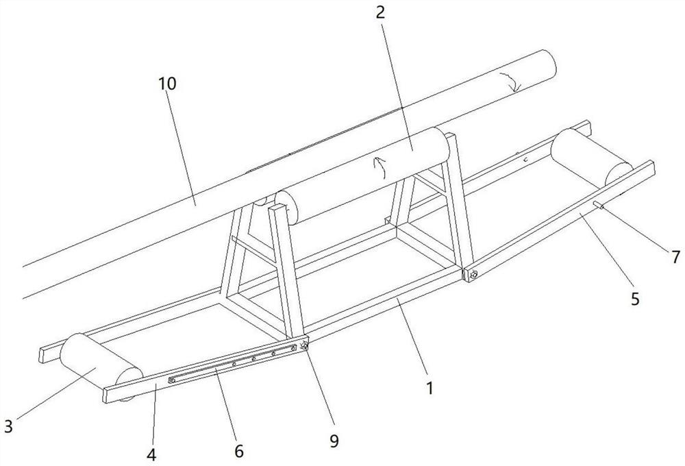
[0022] Such as figure 1 As shown, the push-pull rolling device for auxiliary steel bar connection of the present invention includes a base 1 , a first rotating bracket 4 , a second rotating bracket 5 and a horizontal tie rod 6 .

[0023] The top of the base 1 is provided with two rotating guide wheels 2, the left and right sides of the base 1 are respectively provided with a first rotating bracket 4 and a second rotating bracket 5, and the first rotating bracket 4 and the second rotating bracket 5 are provided with push-pull guide wheels 3 , the push-pull guide wheel 3 is located above the rotating guide wheel 2, and the axis of the push-pull guide wheel 3 is perpendicular to the axis of the rotating guide wheel 2.

[...


PUM


Abstract

The invention relates to a push-pull rolling device for assisting in steel bars connection. The push-pull rolling device comprises a base, a first rotating support, a second rotating support and horizontal pull rods; the top of the base is provided with rotating guide wheels, the left side and the right side of the base are respectively provided with the first rotating support and the second rotating support, the first rotating support and the second rotating support are each provided with a push-pull guide wheel, the push-pull guide wheels are positioned above the rotating guide wheels, and the axes of the push-pull guide wheels are perpendicular to the axes of the rotating guide wheels; the lower ends of the first rotating support and the second rotating support are hinged with the base,and locking bolts are arranged at the hinged positions; and the first rotating support and the second rotating support are fixedly connected through the horizontal pull rods, wherein one end of eachhorizontal pull rod is hinged to the first rotating support, and the other end of each horizontal pull rod is detachably and fixedly connected with the second rotating support. The push-pull rolling device for assisting in steel bar connection not only can solve the problem of vertical push-pull of steel bar cages, but also solves the problem of rotation of the steel bars during mechanical connection.

Description

technical field [0001] The invention relates to an auxiliary tool for steel bar processing, and more particularly, relates to a push-pull rolling device for assisting steel bar connection. Background technique [0002] In the process of producing semi-finished products and finished products, especially the manual rolling of steel cages, the steel bars need to be mechanically connected. Generally, the steel bars are grounded at one end and connected at the other. And it is inefficient, and the connection effect is not good. [0003] Chinese patent CN201710793518.9 discloses a rolling bracket for steel bar processing. The bracket includes a first support and a second support; Crossbeam: a rolling device is set on the upper crossbeam to drive the steel bar to transmit along the direction crossing the upper crossbeam by rolling. It can only be used for steel bar movement, and cannot solve the problem of steel bar rotation and axial movement in the production process of semi-fi...

Claims


Application Information

Patent Timeline
Patent Type & Authority Patents(China)
IPC IPC(8): B21F23/00B21F31/00
CPCB21F23/00B21F31/00
Inventor 王士晓王辉冯祥欧阳毅向建芳
Owner CHINA FIRST METALLURGICAL GROUP
Learn More