
Bolt connection structure and method for connecting low-pressure turbine disk and rotor support cone arm

A technology for rotor support and connecting bolts, which is applied to the supporting elements of blades, engine elements, machines/engines, etc., can solve the problems of falling bolts, unable to provide external support, etc., and achieve the effect of solving self-rotation and simple structure

Active Publication Date: 2018-06-08
AECC COMML AIRCRAFT ENGINE CO LTD
View PDF8 Cites 0 Cited by
  • Summary
  • Abstract
  • Description
  • Claims
  • Application Information

AI Technical Summary

Problems solved by technology

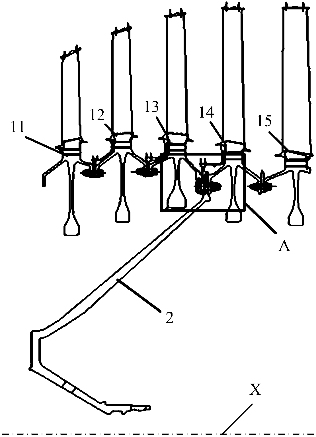
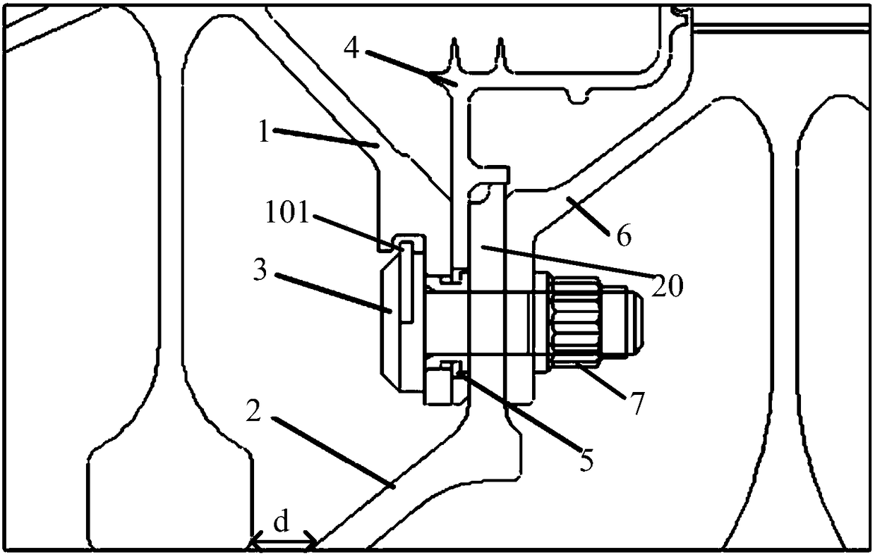
During the assembly of the low-pressure rotor support cone arm, the head of the bolt connecting the low-pressure rotor support cone arm and the front turbine disk faces downward (that is, parallel to the engine axis and backward), but during the assembly process, because the space where the bolt head is located is relatively closed, it cannot Provides external support where the head of the bolt faces downwards causing the bolt to fall out during assembly

Method used


Image

  • Bolt connection structure and method for connecting low-pressure turbine disk and rotor support cone arm
  • Bolt connection structure and method for connecting low-pressure turbine disk and rotor support cone arm
  • Bolt connection structure and method for connecting low-pressure turbine disk and rotor support cone arm

Examples


Embodiment Construction

[0027] The present invention will be further described below in conjunction with specific embodiment and accompanying drawing, set forth more details in the following description so as to fully understand the present invention, but the present invention can obviously be implemented in many other ways different from this description, Those skilled in the art can make similar promotions and deductions based on actual application situations without violating the connotation of the present invention, so the content of this specific embodiment should not limit the protection scope of the present invention. For a shape, its length is greater than its width, which will not be described in subsequent embodiments.

[0028] Figure 4 , Figure 5 , Figure 7 The structures of the first turbine disk, the sealing ring and the connecting bolts in an embodiment of the present invention are respectively shown. It should be noted that these and other subsequent drawings are only examples, w...


PUM


Abstract

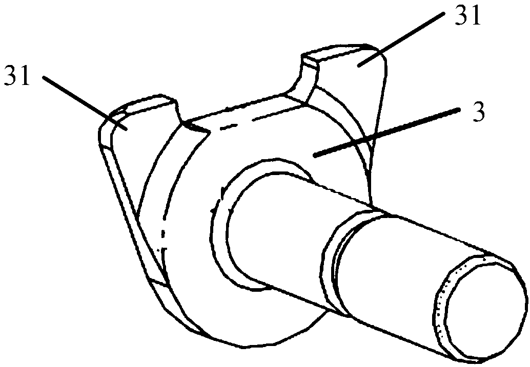
The invention relates to a bolt connecting structure and method connecting a low-pressure turbine disc and a rotor supporting conical arm. The structure is used for connecting a mounting edge of a first turbine disc, a mounting edge of a second turbine disc, a mounting edge of a sealing ring and a mounting edge of the rotor supporting conical arm. The structure comprises a connecting bolt which penetrates through a hole of the mounting edge of the first turbine disc, a hole of the mounting edge of the second turbine disc, a hole of the mounting edge of the sealing ring and a hole of the mounting edge of the rotor supporting conical arm and is fastened by a nut, wherein the hole of the mounting edge of the first turbine disc where the connecting bolt penetrates through is a first hole, the first hole has a first length and a first width, a protruding platform is arranged on the rod portion of the connecting bolt, the protruding platform has a second length and a second width, and the second length is greater than the first width but not greater than the first length, so that the protruding platform can penetrates through the first hole.

Description

technical field [0001] The invention relates to an installation structure and method of an aeroengine turbine rotor, in particular to a bolt connection structure and method for connecting a low-pressure turbine disk and a rotor support cone arm. Background technique [0002] In the assembly process of the low-pressure turbine rotor, vertical assembly is generally adopted, that is, the rear-stage turbine disk is installed on the front-stage turbine disk. During the assembly of the low-pressure rotor support cone arm, the head of the bolt connecting the low-pressure rotor support cone arm and the front turbine disk faces downward (that is, parallel to the engine axis and backward), but during the assembly process, because the space where the bolt head is located is relatively closed, it cannot To provide external support, the bolt head down again can cause the bolt to fall out during assembly. Contents of the invention [0003] The purpose of the present invention is to pro...

Claims


Application Information

Patent Timeline
Patent Type & Authority Patents(China)
IPC IPC(8): F01D5/02
Inventor 廖坚
Owner AECC COMML AIRCRAFT ENGINE CO LTD
Learn More