Surface coating device for automobile body pillar machining

A technology of surface coating and automobile body, which is applied in the direction of surface coating liquid device, pretreatment surface, coating, etc., can solve the problems of column processing influence, column falling off, etc., achieve uniform coating, prevent inconvenience, increase The effect of high friction

Inactive Publication Date: 2019-10-22
十堰市寅云实业有限公司
View PDF0 Cites 2 Cited by
  • Summary
  • Abstract
  • Description
  • Claims
  • Application Information

AI Technical Summary

Problems solved by technology

[0003] However, when the existing device is coating the upright, the upright usually needs to be fixed. However, because the surface of the upright is relatively smooth, the upright may fall off from the device due to vibration when the upright is fixed. Therefore, there is an urgent need for a surface coating device for automobile body column processing to solve such problems

Method used


Image

  • Surface coating device for automobile body pillar machining
  • Surface coating device for automobile body pillar machining
  • Surface coating device for automobile body pillar machining

Examples


Embodiment 1

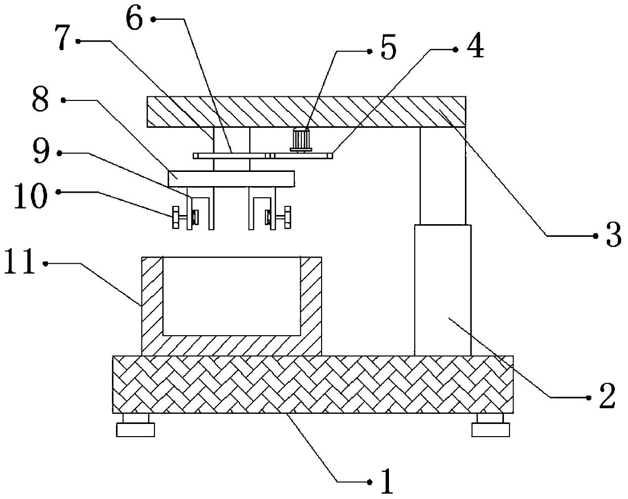
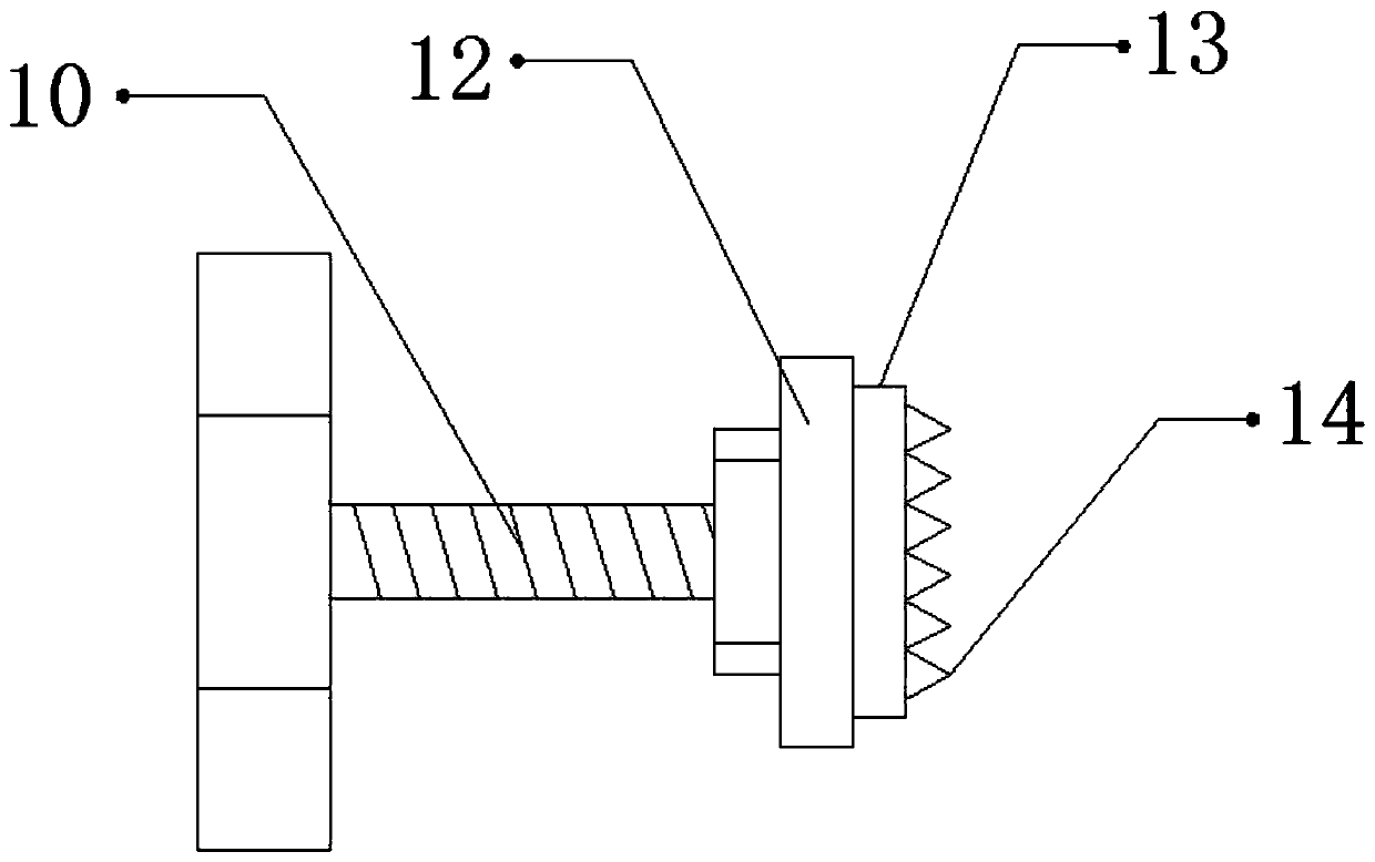
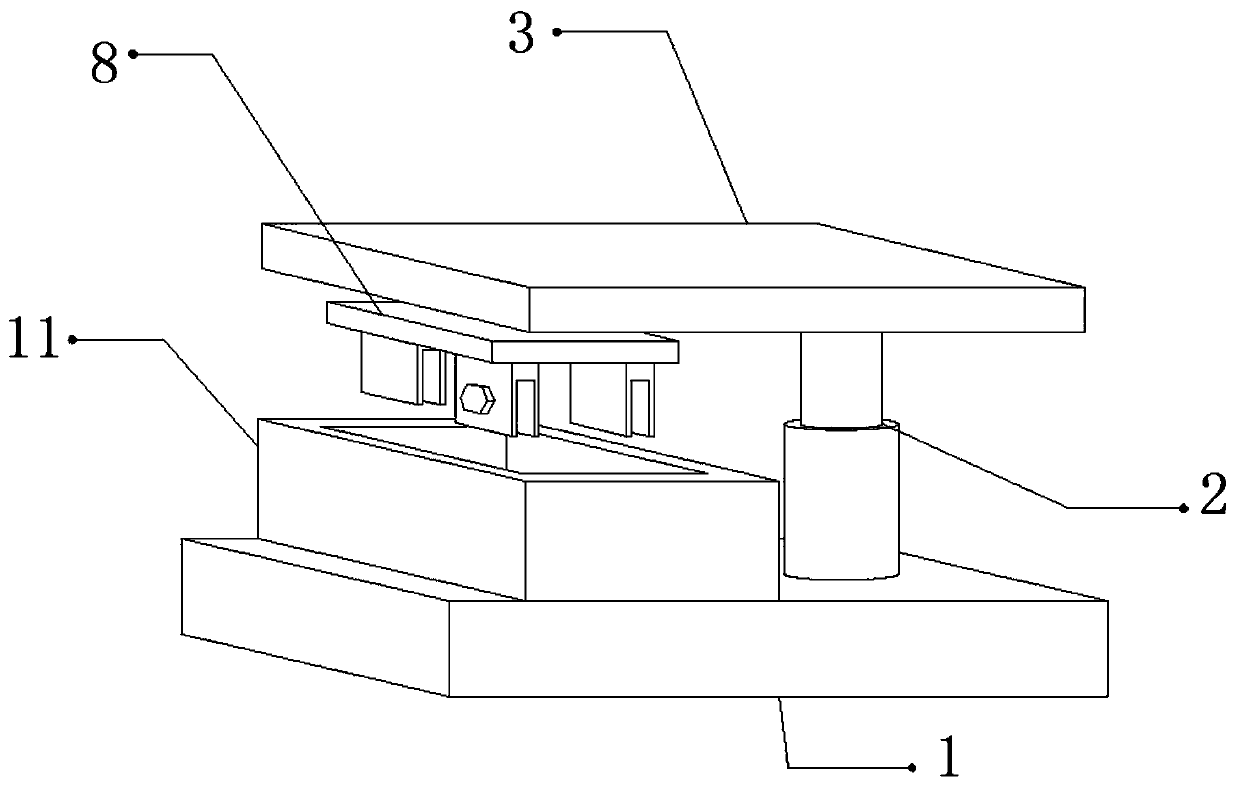
[0026] refer to Figure 1-3 , a surface coating device for automobile body column processing, including a fixed seat 1, one side of the top outer wall of the fixed seat 1 is connected with an electric telescopic rod 2 by bolts, and the top outer wall of the electric telescopic rod 2 is connected with a support plate 3 by bolts , one side of the outer wall at the bottom of the support plate 3 is rotatably connected with a rotating rod 7 through a bearing, and the outer wall at the bottom of the rotating rod 7 is connected with a fixed plate 8 by bolts, and the outer wall at the bottom of the fixed plate 8 is connected with a U-shaped frame 9 by bolts, and the U A side outer wall of the frame 9 has a threaded hole, and the inner wall of the threaded hole is threadedly connected with a fixed bolt 10, and the fixed bolt 10 is connected with a splint 12 through a nut, and the outer wall of the side of the splint 12 is glued with a protective pad 13, and the protective pad One side ...

Embodiment 2

[0030] refer to Figure 4 , a surface coating device for automobile body column processing. Compared with Embodiment 1, one side of the outer wall of the bottom of the support plate 3 is connected with a connecting plate 15 by bolts, and the outer wall of one side of the connecting plate 15 is connected by bolts. There is a dryer 16, and the dryer 16 is electrically connected to the switch.

[0031] Working principle: when in use, put the coating liquid into the collection box 11, and clamp and fix the splint 12 to the column to be coated by twisting the fixing bolt 10, and the protection pad 13 and the fixing teeth 14 can increase the The friction between the large column and the U-shaped frame 9 is convenient for fixing the column, preventing the column from falling off from the U-shaped frame 9 due to the centrifugal force generated during rotation. After the fixing is completed, turn on the switch, and the electric telescopic rod 2 will drive The column moves downward, so...


PUM


Abstract

The invention discloses a surface coating device for automobile body pillar machining. The surface coating device comprises a fixing seat, wherein an electric telescopic rod is fixed on one side of the outer wall of the top of the fixing seat, a supporting plate is fixed on the outer wall of the top of the electric telescopic rod, a rotating rod is rotationally connected to one side of the outer wall of the bottom of the supporting plate through a bearing, a fixing plate is fixed on the outer wall of the bottom of the rotating rod, a U-shaped frame is fixed on the outer wall of the bottom of the fixing plate, a threaded hole is formed in the outer wall of one side of the U-shaped frame, the inner wall of the threaded hole is in threaded connection with a fixing bolt, the fixing bolt is connected with a clamping plate through a nut, and a protective pad is glued on the outer wall of one side of the clamping plate. According to the device, the phenomenon that a pillar falls off from theU-shaped frame due to centrifugal force generated during rotation so as to affect coating of the pillar is prevented, the influence on pillar machining due to the fact that the surface of the pillar is not coated uniformly is avoided, and the problem that the device is inconvenient to clean due to the fact that coating liquid drips on the device can be prevented.

Description

technical field [0001] The invention relates to the technical field of automobile body pillar processing, in particular to a surface coating device for automobile body pillar processing. Background technique [0002] Generally, the body of a car has three pillars, which are the front pillar, the middle pillar, and the rear pillar from front to back. The surface of the column is corroded, and the column is usually coated by a coating device. [0003] However, when the existing device is coating the upright, the upright usually needs to be fixed. However, because the surface of the upright is relatively smooth, the upright may fall off from the device due to vibration when the upright is fixed. Therefore, there is an urgent need for a surface coating device for automobile body column processing to solve such problems. Contents of the invention [0004] The purpose of the present invention is to solve the shortcomings in the prior art, and propose a surface coating device f...

Claims


Application Information

Patent Timeline
Patent Type & Authority Applications(China)
IPC IPC(8): B05C3/09B05C13/02B05C11/10B05D3/02
CPCB05C3/09B05C11/10B05C13/02B05D3/0254
Inventor 张一王正金张永刚
Owner 十堰市寅云实业有限公司
Why Eureka
Try Eureka