Ankle fixing and lifting device
A lifting device and ankle technology, which is applied to stereotaxic surgical instruments, passive exercise instruments, physical therapy, etc., can solve the problems of low degree of freedom of adjustment of leg braces, and achieve the effect of facilitating leg inspection and fine adjustment.
- Summary
- Abstract
- Description
- Claims
- Application Information
AI Technical Summary
Problems solved by technology
Method used
Image
Examples
specific Embodiment approach 1
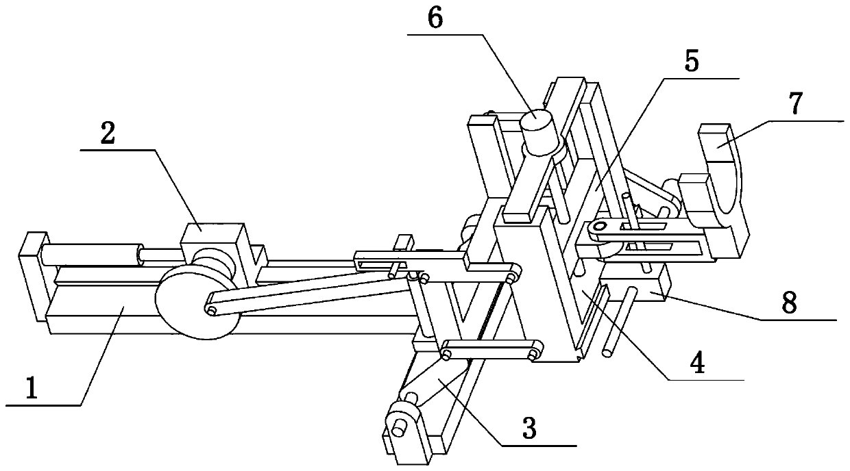
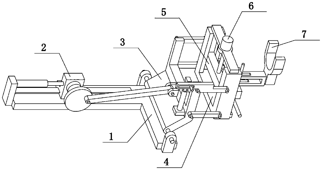
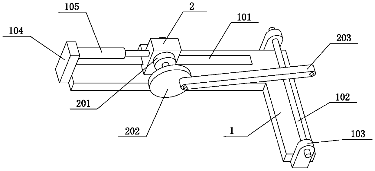
[0031] Combine below Figure 1-7 Describe this embodiment. The present invention relates to the field of orthopedic medicine, more specifically, an ankle-fixing lifting device, which includes a folded plate 3, an upper parallel bar 305, a lower parallel bar 306, a bottom beam 4, a vertical beam 402, a vertical slide Groove 403, horizontal slide bar 5 and U-shaped ankle frame 7, the present invention can erect human ankle, and can lift human ankle, is convenient to carry out leg inspection.
[0032] The front and rear sides of the upper end of the folding plate 3 are hingedly connected with upper parallel rods 305, the front and rear sides of the lower end of the folding plate 3 are hinged with lower parallel rods 306, the upper parallel rods 305 and the lower parallel rods 306 are arranged in parallel, and the bottom beam The front and rear ends of 4 are all fixedly connected with vertical beams 402, and the inner sides of the two vertical beams 402 are all provided with verti...
specific Embodiment approach 2
[0034] Combine below Figure 1-7To illustrate this embodiment, the ankle fixed lifting device also includes an electric telescopic rod II302, an electric telescopic rod seat II303, a sliding cylinder 304, a sliding hole rod 307 and a sliding hole 308, and the folding plate 3 is fixedly connected with an electric telescopic rod seat II303 , the lower end of the electric telescopic rod II302 is fixedly connected to the electric telescopic rod seat II303, the upper parallel rod 305 on the front side is fixedly connected with a sliding hole rod 307, and the sliding hole rod 307 is provided with a sliding hole 308, and the electric telescopic rod II302 A sliding cylinder 304 is fixedly connected to the upper end, and the sliding cylinder 304 is slidably connected to the sliding hole 308 . The electric telescopic rod II302 can be extended or shortened, and then can drive the sliding cylinder 304 to slide on the sliding hole 308, and then drive the sliding hole rod 307 to rotate, and...
specific Embodiment approach 3
[0036] Combine below Figure 1-7 To illustrate this embodiment, the ankle fixed lifting device also includes a motor III6, an upper plate 601 and a lead screw II602, an upper plate 601 is fixedly connected between the upper ends of the two vertical beams 402, and a motor is fixedly connected to the middle of the upper plate 601 III6, a lead screw II602 is fixedly connected to the output shaft at the lower end of the motor III6, and the lead screw II602 cooperates with the horizontal slide bar 5 through threads. When the output shaft of the motor III6 rotates, it can drive the lead screw II602 to rotate around its own axis, thereby controlling the vertical position of the horizontal slide bar 5 .
PUM
 Abstract
Description
Claims
Application Information
 - R&D
- Intellectual Property
- Life Sciences
- Materials
- Tech Scout
- Unparalleled Data Quality
- Higher Quality Content
- 60% Fewer Hallucinations
Browse by: Latest US Patents, China's latest patents, Technical Efficacy Thesaurus, Application Domain, Technology Topic, Popular Technical Reports.
© 2025 PatSnap. All rights reserved.Legal|Privacy policy|Modern Slavery Act Transparency Statement|Sitemap|About US| Contact US: help@patsnap.com


