
Inner compression cold box leakage treatment method

A processing method and internal compression technology, which can be used in refrigeration and liquefaction, heat exchange equipment, liquefaction and other directions, and can solve problems such as safety accidents, cold box foundation damage, and easily damaged equipment.

Inactive Publication Date: 2019-10-18
河南开祥精细化工有限公司
View PDF7 Cites 0 Cited by
  • Summary
  • Abstract
  • Description
  • Claims
  • Application Information

AI Technical Summary

Problems solved by technology

[0003] The leakage treatment of the internal compression cold box in the prior art, the internal compression process used mostly includes air compression, air pre-cooling, molecular sieve purification, supercharged turbo expander refrigeration and rectification separation. The tank is an important equipment of the internal compression oxygen generation system. Its operation is directly related to the operation safety and operation cycle of the internal compression oxygen generation system. Due to various reasons, the equipment in the cold box of the internal compression oxygen generation system is prone to leakage. It is easy to damage the equipment or cause various safety accidents. At the same time, the leaked cryogenic liquid will often cause damage to the foundation of the cold box. Therefore, it is urgent to develop a leakage treatment method for the internal compression cold box

Method used


Image

  • Inner compression cold box leakage treatment method
  • Inner compression cold box leakage treatment method

Examples


Embodiment Construction

[0026] In order to make the above objects, features and advantages of the present invention more comprehensible, specific implementations of the present invention will be described in detail below in conjunction with the accompanying drawings.

[0027] In the following description, a lot of specific details are set forth in order to fully understand the present invention, but the present invention can also be implemented in other ways different from those described here, and those skilled in the art can do it without departing from the meaning of the present invention. Similarly generalized, the present invention is therefore not limited by the specific embodiments disclosed below.

[0028] Secondly, the present invention is described in detail in combination with schematic diagrams. When describing the implementation of the present invention in detail, for the convenience of explanation, the cross-sectional view showing the device structure will not be partially enlarged accor...


PUM


Abstract

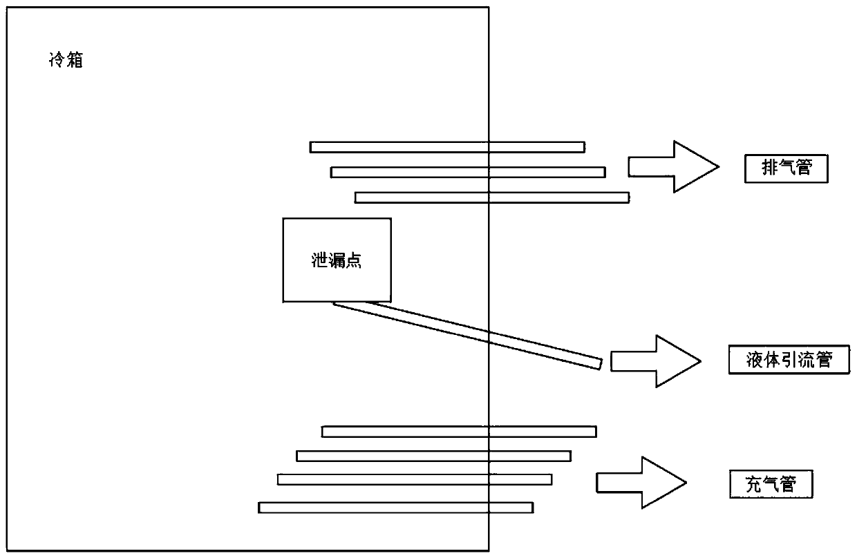
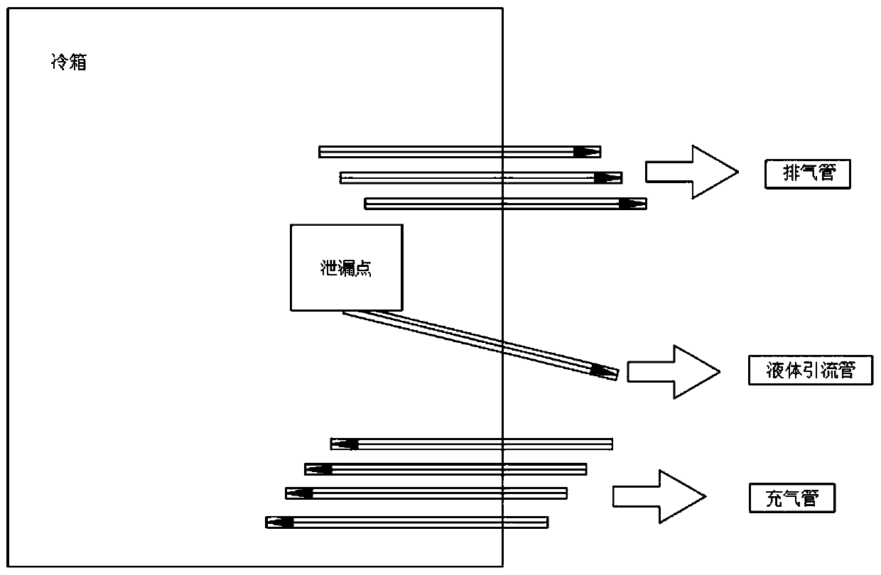
The invention belongs to the technical field of air separation equipment, and particularly relates to an inner compression cold box leakage treatment method. The internal compression cold box leakageprocessing method comprises the following steps of 1, making data analysis; 2, confirming a leakage position; 3, punching and draining; and 4, inserting an air pipe. In the step 1, through the foundation temperature condition, gas component analysis in a cold box, and the comprehensive check of ventilation holes in the lower part of the cold box and the wall surface of the cold box, whether leakage exists in the cold box or not is judged, the leakage size, the approximate leakage direction and the leakage medium are judged; in the step 2, the leakage position possibly existing in the cold boxis confirmed through a pipeline diagram, and finally the specific leakage position is determined; in the step 3, after the leakage position is determined, the on-line cold box punching is used for guiding liquid to the outside of the cold box through a liquid drainage pipe; and in the step 4, the air pipe is inserted above the leakage point, and the air pipe is inserted below the leakage point. According to the inner compression cold box leakage treatment method, the leakage of the low-temperature liquid can be effectively prevented, the protection of a cold box foundation is realized, and the comprehensive effect of safety accidents is reduced.

Description

technical field [0001] The invention relates to the technical field of air separation equipment, in particular to a method for treating leakage of an internally compressed cold box. Background technique [0002] At present, the air separation unit is a device that uses air as a raw material, turns the air into a liquid state through a compression cycle deep freezing method, and then gradually separates it from the liquid air through rectification to produce gas products such as oxygen, nitrogen, and argon. In air separation technology, the process of producing high-pressure oxygen directly from the air separation equipment to supply users is called the internal compression process. [0003] The leakage treatment of the internal compression cold box in the prior art, the internal compression process used mostly includes air compression, air pre-cooling, molecular sieve purification, supercharged turbo expander refrigeration and rectification separation. The tank is an import...

Claims


Application Information

Patent Timeline
Patent Type & Authority Applications(China)
IPC IPC(8): F25J3/04F28F11/00
CPCF25J3/04048F28F11/00F25J3/04854F25J3/04945
Inventor 侯祥斌王磊李建立和进伟赵宁张方李艳红郭彪李健季飞冯期张庆华张志伟周鹏飞尚凤玲
Owner 河南开祥精细化工有限公司
Learn More