Crushing deformation type rear-end crash seat energy-absorbing structure
An energy-absorbing structure and seat technology, which is applied to vehicle seats, movable seats, special positions of vehicles, etc., can solve problems such as unstable force, poor energy-absorbing effect, and high difficulty in energy-absorbing structure design, and achieve cushioning The process of energy absorption is stable and the effect of reducing occupant damage
- Summary
- Abstract
- Description
- Claims
- Application Information
AI Technical Summary
Problems solved by technology
Method used
Image
Examples
Embodiment 1
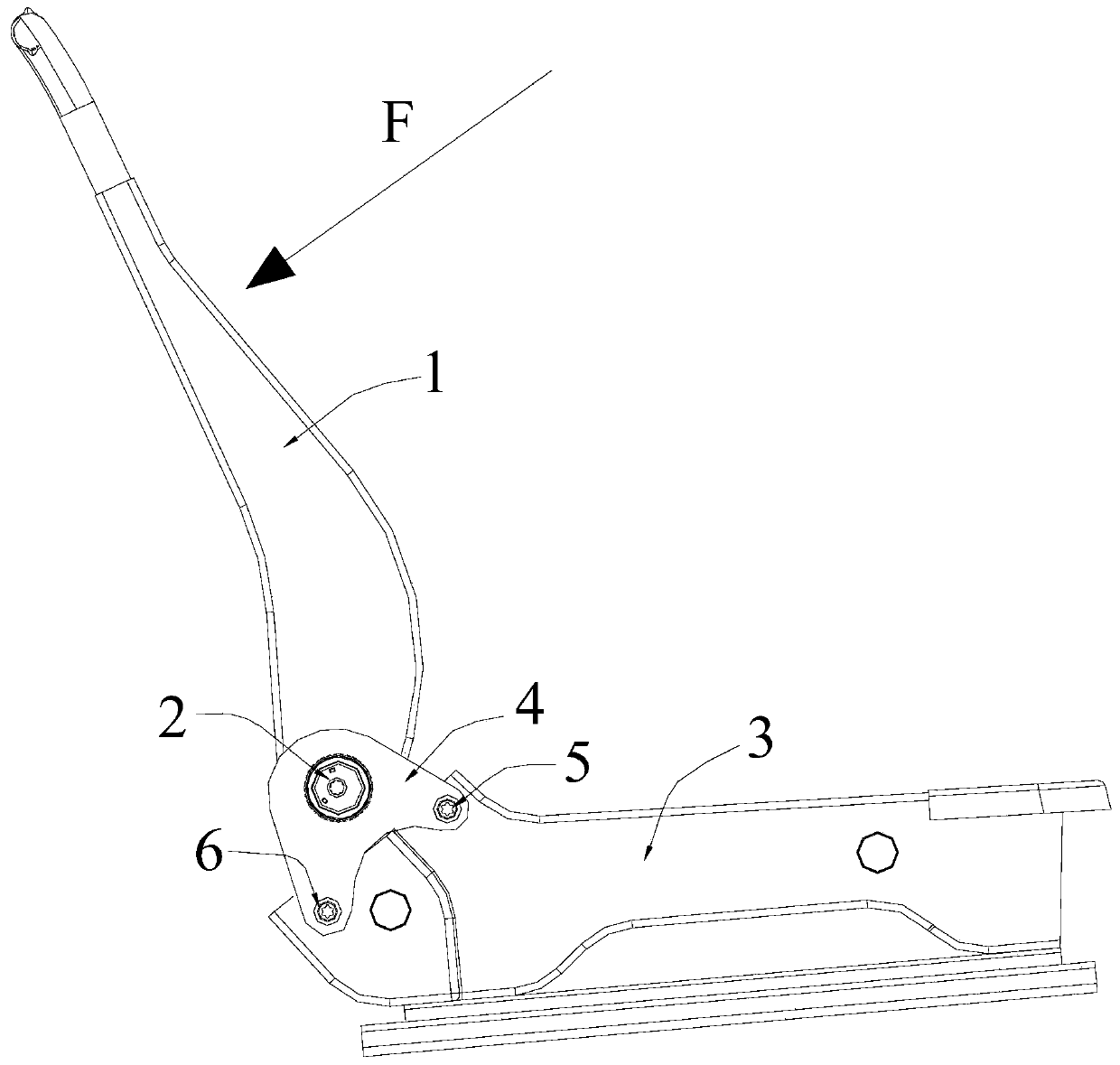
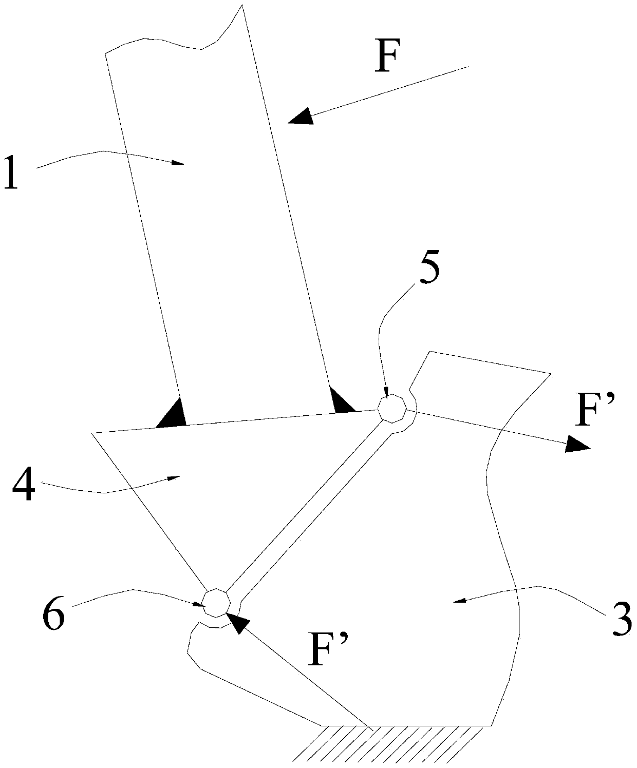
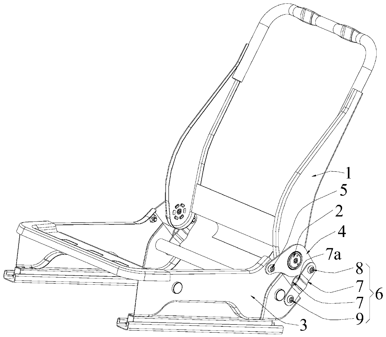
[0043] Such as image 3 only Figure 13As shown, the present invention discloses an energy-absorbing structure for a rear-end collision seat, including a seat cushion side plate 3 and a recliner connecting plate 4, the front end of the recliner connecting plate 4 and the rear portion of the seat cushion side plate 3 The upper end is connected to form a first connection structure 5, and the rear end of the recliner connecting plate 4 is connected to the rear lower end of the seat cushion side plate 3 to form a second connection structure 6, wherein the first connection structure 5 is a bolt connection structure;
[0044] The second connection structure 6 is an energy-absorbing connection structure composed of an energy-absorbing plate 7 , an upper-end bolt connection structure 8 and a lower-end bolt connection structure 9 , and the upper end of the energy-absorbing plate 7 is connected through the upper-end bolt connection structure 8 The rear end of the recliner connecting p...
Embodiment approach
[0052] Such as Image 6 , Figure 8 with Figure 9 As shown, the energy absorbing plate 7 is composed of an upper plate part 7-1, a single-sided middle plate part 7-2 and a lower plate part 7-3 connected in sequence, and the upper plate part 7-1 and the lower plate part The plate portions 7-3 are coplanar, and the single-sided middle plate portion 7-2 protrudes toward the cushion side plate 3, that is, the left or right direction of the car seat, to form the concave-convex structure 7a; , the upper end and the lower end of the energy-absorbing plate 7 are respectively located on the upper plate portion 7-1 and the lower plate portion 7-3.
[0053] The above is the basic implementation mode of the second embodiment, further optimization, improvement and limitation can be done on the basis of the basic implementation mode:
[0054] Preferably: the cross-sectional shape of the single-sided middle plate portion 7-2 is arc-shaped (see Image 6 ), rectangular half (see Figure ...
Embodiment 3
[0056] On the basis of the above-mentioned embodiment 1, the present embodiment 3 also adopts the following preferred implementation modes:
[0057] Such as Figure 10 , Figure 11 with Figure 12 As shown, the energy-absorbing plate 7 is composed of an upper plate part 7-1, a double-sided middle plate part 7-4 and a lower plate part 7-3 connected in sequence, and the upper plate part 7-1 and the lower plate part The plate parts 7-3 are in the same plane, and the double-sided middle plate part 7-4 is composed of a connected upper end middle plate part 7-4-1 and a lower end middle plate part 7-4-2, and the upper end middle plate part 7 -4-1 is connected with the upper plate part 7-1, the lower middle plate part 7-4-2 is connected with the lower plate part 7-3, the upper middle plate part 7-4-1 and the lower end One of the middle plate parts 7-4-2 protrudes toward the left side of the cushion side plate 3, that is, the car seat, and the other protrudes toward the right side o...
PUM
 Abstract
Description
Claims
Application Information
 - R&D
- Intellectual Property
- Life Sciences
- Materials
- Tech Scout
- Unparalleled Data Quality
- Higher Quality Content
- 60% Fewer Hallucinations
Browse by: Latest US Patents, China's latest patents, Technical Efficacy Thesaurus, Application Domain, Technology Topic, Popular Technical Reports.
© 2025 PatSnap. All rights reserved.Legal|Privacy policy|Modern Slavery Act Transparency Statement|Sitemap|About US| Contact US: help@patsnap.com


