
Rubber cutting equipment for rubber production

A technology of cutting glue and equipment, applied in metal processing and other directions, can solve the problems of no good, cutting deviation production, inconvenient use, etc., to achieve the effect of facilitating taking and collecting, avoiding offset and improving accuracy

Inactive Publication Date: 2019-10-18
滁州君越高分子新材料有限公司
View PDF9 Cites 5 Cited by
  • Summary
  • Abstract
  • Description
  • Claims
  • Application Information

AI Technical Summary

Problems solved by technology

[0002] The rubber industry is one of the important basic industries of the national economy. At the same time, there are many applications of rubber. It provides daily-use, medical and other light industrial rubber products that are indispensable to daily life. Emerging industries provide a variety of rubber production equipment or rubber parts, which are used in all walks of life. The rubber industry has a wide variety of products, and the backward industry is very broad. At present, the rubber raw materials need to be cut into strips or cut in the rubber production process. Now Some glue cutting equipment is inconvenient to adjust the cutter, and it is inconvenient to use, and there is no good clamping device when cutting strips or cutting, which may easily lead to deviations during cutting and affect subsequent production, and there is no good solution at present. method

Method used


Image

  • Rubber cutting equipment for rubber production
  • Rubber cutting equipment for rubber production
  • Rubber cutting equipment for rubber production

Examples


Embodiment Construction

[0021] In order to make the technical means, creative features, goals and effects achieved by the present invention easy to understand, the present invention will be further described below in conjunction with specific embodiments.

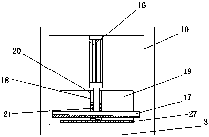
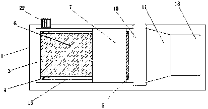
[0022] see Figure 1-4 , the present invention provides a technical solution: a rubber cutting equipment for rubber production, including a base plate 1, a support 2, a first electro-hydraulic push rod 14 and a collection box 13 are fixed on the top of the base plate 1 in sequence, and a support 2 is fixed on the top of the support 2 Cutting table 3, the top of cutting table 3 is provided with band groove 15, and the side wall of cutting table 3 is fixed with limiting shell 7 and frame 10, and the top inside frame 10 is equipped with hydraulic press 16, and the piston rod end of hydraulic press 16 is fixed with Cutting piece 17, the piston rod side wall of hydraulic machine 16 is fixed with slide block 18, and slide block 18 is positioned at the i...


PUM


Abstract

The invention discloses rubber cutting equipment for rubber production. The equipment comprises a base plate, wherein the top end of the base plate is sequentially and fixedly provided with a bracket,a first electric-hydraulic push rod and a collecting box, the top end of the bracket is fixedly provided with a cutting table, and a belt groove is formed in the top end of the cutting table. The side wall of the cutting table is fixedly provided with a limiting shell and a machine frame, wherein the top of the inside of the machine frame is provided with a hydraulic machine, and the tail end ofa piston rod of the hydraulic machine is fixedly provided with a cutting blade. The side wall of the piston rod of the hydraulic machine is fixedly provided with a sliding block, wherein the sliding block is located in a sliding groove, the sliding groove is formed in the side surface of an abutting plate, and the bottom end of the inside of the sliding groove is provided with a spring. Accordingto rubber cutting equipment for rubber production, the side wall of the piston rod of the hydraulic machine is fixedly provided with a sliding block, and the sliding block is located in the sliding groove formed in the abutting plate, so that when the hydraulic machine drives the cutting blade to conduct cutting, the abutting plate abuts against a rubber piece, so that the rubber piece is tightlypressed, the occurrence of skewing when the cutting is undergoing is greatly avoided, the cutting precision is improved, and thereforethe rubber cutting equipment for rubber production is suitable forwide popularization and application.

Description

technical field [0001] The invention relates to a rubber cutting device, in particular to a rubber cutting device for rubber production. Background technique [0002] The rubber industry is one of the important basic industries of the national economy. At the same time, there are many applications of rubber. It provides daily-use, medical and other light industrial rubber products that are indispensable to daily life. Emerging industries provide a variety of rubber production equipment or rubber parts, which are used in all walks of life. The rubber industry has a wide variety of products, and the backward industry is very broad. At present, the rubber raw materials need to be cut into strips or cut in the rubber production process. Now Some glue cutting equipment is inconvenient to adjust the cutter, and it is inconvenient to use, and there is no good clamping device when cutting strips or cutting, which may easily lead to deviations during cutting and affect subsequent pro...

Claims


Application Information

Patent Timeline
Patent Type & Authority Applications(China)
IPC IPC(8): B26D1/08B26D7/06B26D7/02B26D7/32
CPCB26D1/08B26D7/02B26D7/06B26D7/0625B26D7/32
Inventor 任兆军
Owner 滁州君越高分子新材料有限公司
Learn More