Metal pipe fitting casting device and casting method

A technology for metal pipe fittings and round pipes, which is applied in the field of metal pipe fitting casting devices, can solve problems such as difficult demoulding, and achieve the effects of rapid demoulding and solving difficult demoulding.

Active Publication Date: 2021-10-29
山东金汇铸造机械有限公司
View PDF9 Cites 0 Cited by
  • Summary
  • Abstract
  • Description
  • Claims
  • Application Information

AI Technical Summary

Problems solved by technology

[0003] The purpose of the present invention is to provide a casting device and casting method for metal pipe fittings, which can effectively solve the problem that the metal pipe fittings in the prior art are not easy to demould after casting; Metal pipe fittings casting mold, after the metal pipe frame casting is completed, the rapid demoulding of metal pipe fittings can be realized by controlling the separation of the round rod mold and the round pipe mold

Method used


Image

  • Metal pipe fitting casting device and casting method
  • Metal pipe fitting casting device and casting method
  • Metal pipe fitting casting device and casting method

Examples


specific Embodiment approach 1

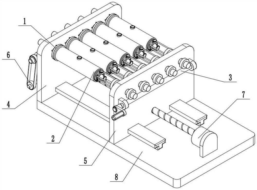
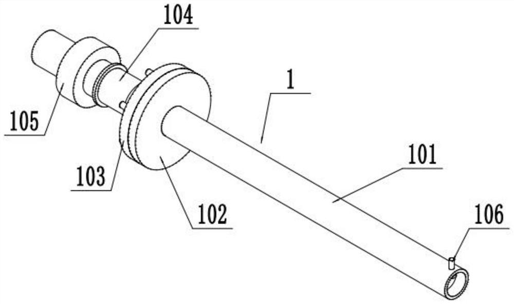
[0033] Such as Figure 1-11 As shown, a metal pipe casting device includes a round rod mold 1, a round pipe mold 2, a hand control mechanism 3, a fixed stand 4, a movable stand 5, a linkage wheel set 6, a drive mechanism 7 and a frame 8, Described round bar mold 1 is provided with a plurality of, and the left end of a plurality of round bar molds 1 is rotatably connected on the fixed stand 4; On the movable stand 5; the right end of a plurality of round rod molds 1 rotates and fits on the left end of a plurality of round tube molds 2; the fixed stand 4 is fixed on the left end of the top surface of the frame 8; the movable stand 5 slides Cooperate with the right end of frame 8 top surface; Described drive mechanism 7 is connected on the right end of frame 8; on the frame 4; the driving mechanism 7 is connected to the linkage wheel set 6; the linkage wheel set 6 is connected to the fixed stand 4; the linkage wheel set 6 is connected to a plurality of round rod molds 1 through ...

specific Embodiment approach 2

[0035] Such as Figure 1-11 As shown, the frame 8 is provided with a T-shaped slide rail 801; the movable stand 5 is slidably fitted on the T-shaped slide rail 801 through a T-shaped slot. The setting of the T-shaped slide rail 801 can improve the stability of the movable stand 5 when sliding on the frame 8 .

specific Embodiment approach 3

[0036] Such as Figure 1-11 As shown, the drive mechanism 7 includes a servo motor 701, a lead screw 702 and a transmission bevel gear 703; the servo motor 701 is fixed on the frame 8 through a motor base; the output shaft of the servo motor 701 is connected by a coupling One end of the lead screw 702 , the lead screw 702 is rotatably fitted on the fixed stand 4 , and the other end of the lead screw 702 is fixedly connected to the transmission bevel gear 703 ; After the servo motor 701 inside the drive mechanism 7 is powered on, it can drive the lead screw 702 to rotate. When the lead screw 702 rotates, it can drive the transmission bevel gear 703 to rotate, and the transmission bevel gear 703 can drive the linkage wheel group 6 to work; When the leading screw 702 rotates, the position where the leading screw 702 contacts with the movable stand 5 changes, and then drives the movable stand 5 to slide on the frame 8 .


PUM


Abstract

A casting device and casting method for metal pipe fittings of the present invention, the method comprises the following steps: 1. Open the driving mechanism, the driving mechanism drives the movable stand to slide on the frame, and the movable stand drives a plurality of round pipe molds to a plurality of round rods The direction of the mold moves and cooperates with multiple parts to form a metal pipe fitting casting mold; 2. The metal solution is injected into the metal pipe fitting casting mold composed of a round pipe mold and a round rod mold through a round pipe mold, and air-cooled equipment or placed in a low temperature Cooling and forming in the environment; 3. After cooling and forming, the control drive mechanism drives the movable stand to move in the opposite direction to the fixed stand, and the movable stand drives multiple round tube molds to separate from multiple round rod molds. The cooperation of the pipe mold and the plurality of round bar molds is used to eject and demould the plurality of metal pipe fittings, and the inner wall of the metal pipe fittings is smoothed and polished through the plurality of round bar molds; the metal pipe fittings are obtained.

Description

technical field [0001] The invention relates to the field of casting equipment, in particular to a casting device and a casting method for metal pipe fittings. Background technique [0002] Casting is a kind of metal thermal processing technology mastered by human beings earlier, with a history of about 6,000 years. China has entered the heyday of bronze castings between 1700 BC and 1000 BC, and the craftsmanship has reached a very high level. Casting refers to the processing method of melting solid metal into liquid and pouring it into a mold of a specific shape, and waiting for it to solidify and form. Metal pipe is one of the common pipe materials used in construction. During the casting process of metal pipe, there is a problem that it is not easy to demould after casting, which seriously affects the production and processing efficiency of metal pipe fittings. Contents of the invention [0003] The purpose of the present invention is to provide a casting device and c...

Claims


Application Information

Patent Timeline
Patent Type & Authority Patents(China)
IPC IPC(8): B22D25/02B22D27/04B22D31/00B22D29/08
CPCB22D25/02B22D27/04B22D29/08B22D31/007
Inventor 王甜
Owner 山东金汇铸造机械有限公司
Why Eureka
Try Eureka