C-shaped closed angle beam forming tool and demolding method

A technology for forming tooling and closing angles, which is applied to household components, household appliances, other household appliances, etc., can solve the problems of easy damage to the surface of composite parts, high manufacturing and use costs, and bending of composite parts, saving manpower. The effect of operating time cost, reduction of mold release equipment, and reduction of manufacturing difficulty

Inactive Publication Date: 2021-12-28
GUANGLIAN AVIATION IND CO LTD
View PDF10 Cites 0 Cited by
  • Summary
  • Abstract
  • Description
  • Claims
  • Application Information

AI Technical Summary

Problems solved by technology

[0003] Commonly used demoulding methods have their own characteristics, functions and use environments, but there are also great shortcomings. The usual lifting method of demoulding is very simple and convenient, but it is particularly easy to damage the surface of composite parts; using the method of setting lifting points method, during the lifting process, composite parts may be bent or even damaged due to uneven force and improper operation
According to different tooling, special demoulding devices can be designed. The manufacturing and use costs of special demoulding devices are relatively high, and the versatility is poor

Method used


Image

  • C-shaped closed angle beam forming tool and demolding method
  • C-shaped closed angle beam forming tool and demolding method
  • C-shaped closed angle beam forming tool and demolding method

Examples


specific Embodiment approach 1

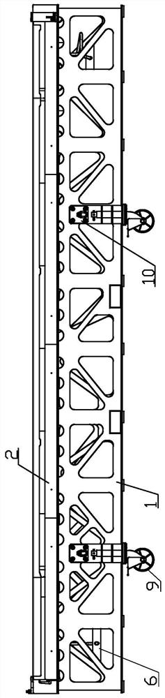
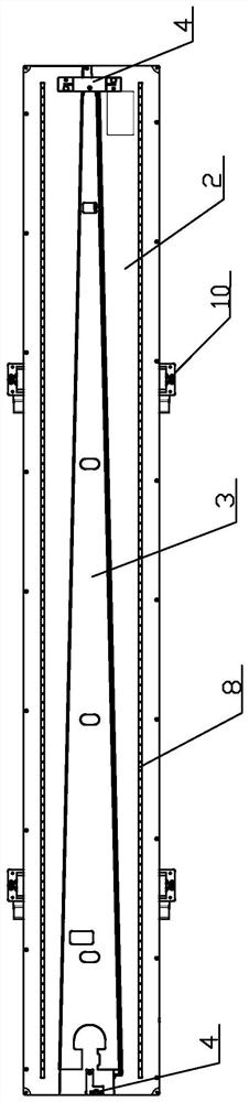
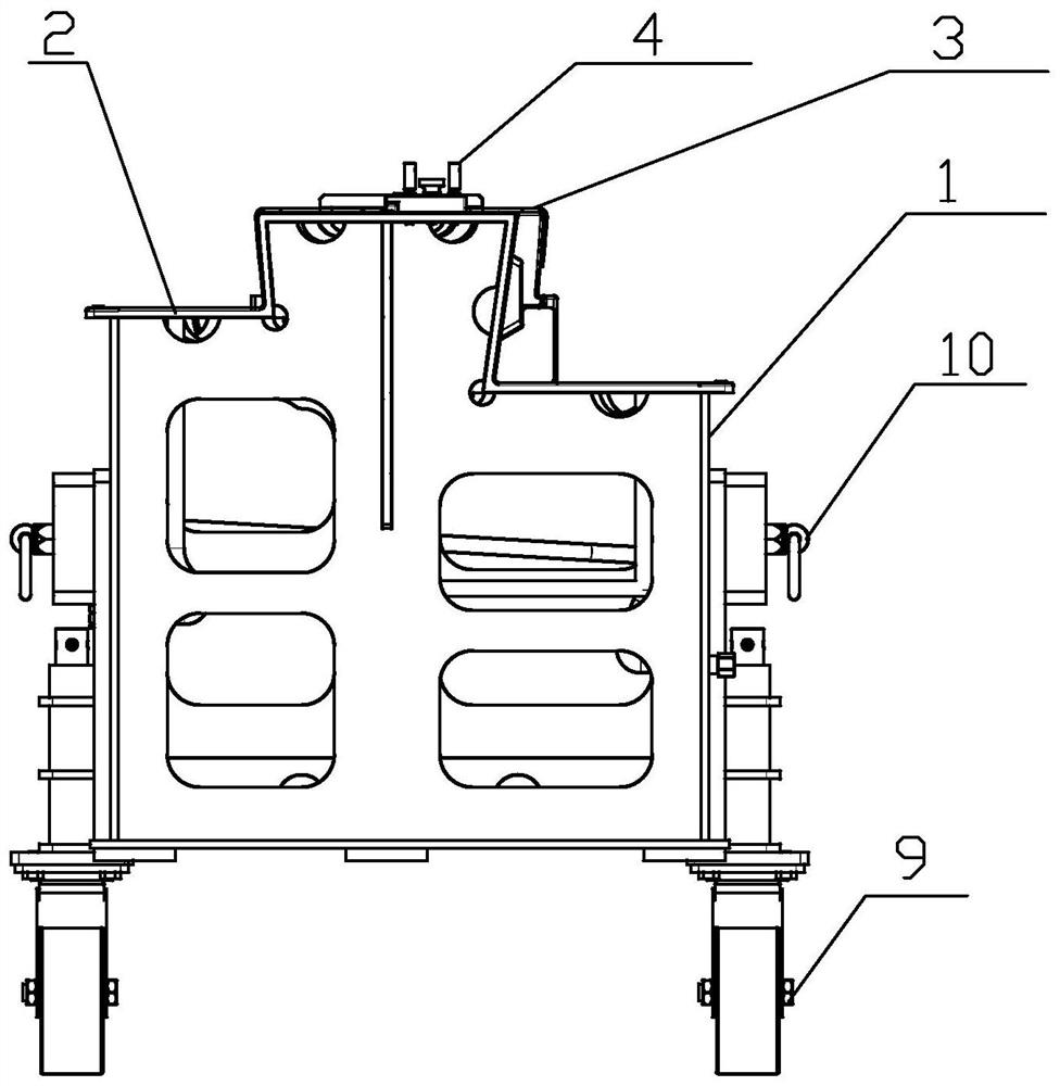
[0031] A C-shaped closed-angle beam forming tooling includes a frame 1 and a mold assembly 2, the mold assembly includes a plate one 21, a plate two 22, a plate three 23, a sub-block 24 and an insert 25, the plate one 21, plate The second plate 22 and the third plate 23 are sequentially connected to form a 'C'-shaped structure, the free ends of the first plate 21 and the third plate 23 are all inclined inwardly and fixed on the frame 1, and the sub-blocks 24 are arranged on the third plate 23 One side, and the upper surface is flush with the second plate 22 , the sub-block 24 is set inwardly away from the lower end of the side wall of the third plate 23 , and the insert 25 is arranged below the sub-block 24 .

[0032] Further, the acute angle between the side wall of the block 24 away from the third plate 23 and the vertical direction is greater than the acute angle between the edge strip 31 of the C-shaped closed angle beam 3 and the vertical direction.

[0033] Further, the ...

specific Embodiment approach 2

[0041] A method for demoulding a C-shaped closed-angle beam using the forming tool described in Embodiment 1, comprising the following steps:

[0042] Step 1. After the C-shaped closed-angle beam 3 is cured and molded in the autoclave on the molding tool, the tool is transferred to the open space to prepare for demoulding. First, the auxiliary materials used for curing the vacuum bag, isolation film, twist strip, etc. Peel it off from the tooling, and drill the craft lug hole at the reserved position of the drilling mold;

[0043] Step 2. When demoulding, take out the lower insert 25 along the width direction of the tooling;

[0044] Step 3, the demoulding block 24 is moved downwards, and then taken out along the width direction of the tooling to complete the demoulding of the C-shaped closed-angle beam.

[0045] Before designing the mold, measure the closed angle of the part (the acute angle between the edge strip 31 and the vertical direction) to be 5°, and the angle betwee...


PUM


Abstract

The invention discloses a C-shaped closed angle beam forming tool and a demolding method, and belongs to the technical field of aeronautical material forming. The specific scheme is as follows: the C-shaped closed angle beam forming tool comprises a frame and a mold assembly, the mold assembly comprises a first plate, a second plate, a third plate, a sub-block and an insert, the first plate, the second plate and the third plate are sequentially connected to form a C-shaped structure, the free end of the first plate and the free end of the third plate incline inwards and are fixed to the frame, the sub-block is arranged on one side of the third plate, the upper surface of the sub-block is flush with the second plate, the lower end of the side wall, away from the third plate, of the sub-block inclines inwards, and the insert is arranged below the sub-block. A demolding tool is simple in structure and convenient to use, and the time cost of manual operation is saved; compared with an original demolding mode, a special demolding device is omitted, meanwhile, the mold manufacturing difficulty is greatly reduced, and the cost is greatly reduced; and the problem that a C-shaped closed angle beam composite material part is not easy to demould is solved, and the part cannot be damaged.

Description

technical field [0001] The invention belongs to the technical field of aviation material forming, and in particular relates to a C-shaped closed-angle beam forming tool and a demoulding method. Background technique [0002] As aircraft structural parts are developing toward integration, large-scale, and complex theoretical shapes, almost all double-sided parts have at least one closed angle, and many parts have excessive local closed angles. Most of the aircraft mechanism components use Composite materials, the superior properties of composite materials make them more and more widely used in the aviation field. More and more large-size, super-large and high-precision composite parts of C-beam composite parts are selected to be solidified. The beam depends on the aircraft section, so most parts may also have closed angles, often such closed angles (the closed angle of the beam means that the angle between the web and the edge of the inner surface of the part is less than 90°)...

Claims


Application Information

Patent Timeline
Patent Type & Authority Applications(China)
IPC IPC(8): B29C33/44B29L31/30
CPCB29C33/44B29L2031/3076
Inventor 薛奥姜海洋朱清文杨守吉王利张晓艳赵清
Owner GUANGLIAN AVIATION IND CO LTD
Why Eureka
Try Eureka