Laryngoscope cannula and laryngoscope

A laryngoscope and intubation technology, applied in the field of laryngoscope intubation and laryngoscope, can solve the problems of laryngoscope blade waste, contamination of the upper end of the handle, waste of time adjustment, etc., and achieve the effect of avoiding cross infection and eliminating cross infection

Pending Publication Date: 2019-10-18
ZHEJIANG UE MEDICAL
View PDF1 Cites 3 Cited by
  • Summary
  • Abstract
  • Description
  • Claims
  • Application Information

AI Technical Summary

Problems solved by technology

When the doctor examines different patients, it will waste time to adjust the length of the laryngoscope handle to match the laryngoscope blade, thereby reducing medical efficiency, and the laryngoscope blade used may not match the patient, resulting in waste of laryngoscope blades
Secondly, the shape of the top of the laryngoscope at the position of the protective handle is relatively smooth. When the doctor holds the laryngoscope or the patient vomits during treatment, the upper end of the handle may be polluted, thus causing cross-infection

Method used


Image

  • Laryngoscope cannula and laryngoscope
  • Laryngoscope cannula and laryngoscope
  • Laryngoscope cannula and laryngoscope

Examples


Embodiment Construction

[0031] Below through specific embodiment, in conjunction with accompanying drawing, the present invention or the technical solution of the invention are described further in detail;

[0032] In the description of the present invention, it should be understood that the orientation or positional relationship indicated by the terms "near", "far", "top", "inner", "outer" etc. is based on the orientation or positional relationship shown in the drawings , is only for the convenience of describing the present invention and simplifying the description, but does not indicate or imply that the device or element referred to must have a specific orientation, be constructed and operated in a specific orientation, and therefore cannot be construed as limiting the present invention; in this application , the proximal end should be interpreted as the part close to the operator (doctor), while the distal end should be understood as the part away from the doctor.

[0033] In the description of ...


PUM


Abstract

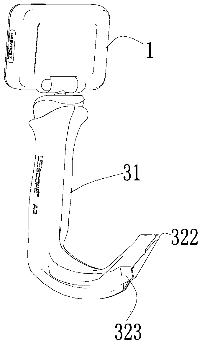
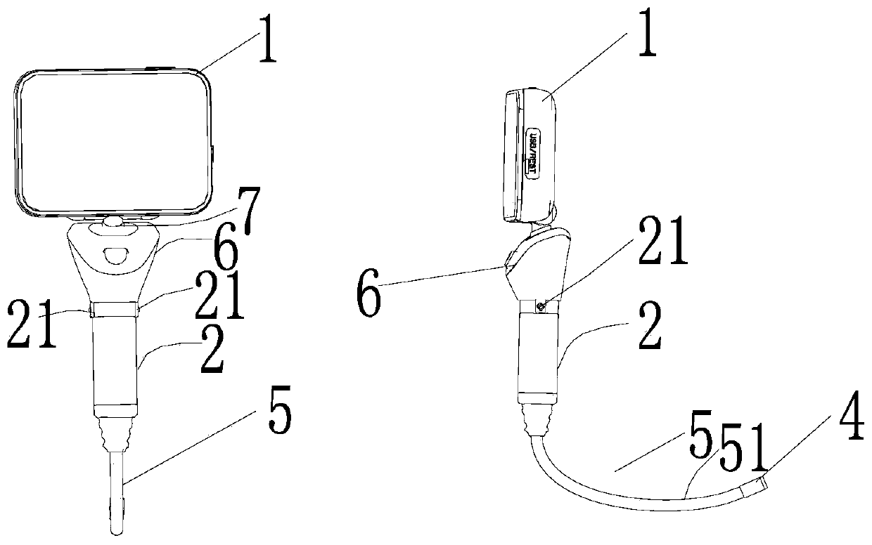
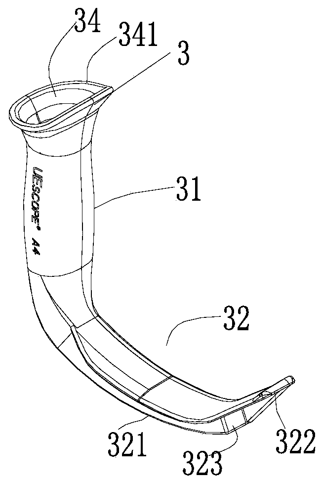
The invention provides a video laryngoscope. The video laryngoscope comprises a repeatedly-used camera shooting assembly, a repeatedly-used display assembly, a repeatedly-used rod, a repeatedly-used flexible connection line and a disposable laryngoscope cannula. The rod has a fixed extension height a, the flexible connection line penetrates through the rod and is connected with the display assembly and provided with an embedding segment located at the rod and an exposure segment protruding out of the far end of the rod, and the exposure segment has a fixed extension length b; the camera shooting assembly is installed at the far end of the exposure segment; the disposable laryngoscope cannula is internally provided with a channel running through a handle segment, a transition segment and abase, and the channel is used for containing the rod and the exposure segment of the flexible connection line, so that the camera shooting assembly abuts against the far end of the channel of the base; the far end of the base is sealed by a transparent material; an extension length h between the near end of the rod and the far end of the flexible connection line is about equal to an extension length m between the near end of the channel and the far end of the channel; an extension height c of the channel running through the handle segment is greater than or equal to the extension length a of the rod.

Description

technical field [0001] The invention belongs to the technical field of medical instruments, in particular to a laryngoscope intubation tube and a laryngoscope comprising the laryngoscope intubation tube. Background technique [0002] With the advancement of medical device technology, laryngoscopes have become an essential medical device in hospitals. The existing laryngoscopes include mirror handles and lenses. The lenses are installed on the matching handles to ensure that the lenses are fixed on the handles. The mirror handle is used repeatedly, and the lens has a large lens, a medium lens and a small lens. The large lens is mostly used for adult men, the medium lens is mostly used for adult women, and the small lens is mostly used for children and teenagers. , put the patient on his back, tilt his head back as far as possible, and enter the oral cavity along the right corner of the mouth with the laryngoscope in his left hand; slowly push the lens to the base of the tongu...

Claims


Application Information

Patent Timeline
Patent Type & Authority Applications(China)
IPC IPC(8): A61B1/267A61B1/05A61B1/06
CPCA61B1/267A61B1/05A61B1/0684
Inventor 田志红江春才黄运东
Owner ZHEJIANG UE MEDICAL
Why Eureka
Try Eureka