
Woven fabric cleaning and drying device

A drying device and spinning technology, which is used in liquid/gas/vapor treatment transmission, textile and papermaking, textile material processing, etc., can solve the problem that the transmission roller does not have an anti-slip device, reduces production efficiency, and the spinning cloth cannot be driven. and other problems to achieve the effect of changing the anti-slip limit, improving production efficiency and preventing slippage

Inactive Publication Date: 2019-10-15
毛祥溪
View PDF4 Cites 3 Cited by
  • Summary
  • Abstract
  • Description
  • Claims
  • Application Information

AI Technical Summary

Problems solved by technology

[0003] The transmission roller is mainly composed of a driving wheel and a driven wheel. The textile is sandwiched between the driving wheel and the driven wheel. The driving wheel rotates under the drive of the motor, and the driving wheel drives the textile and the driven wheel to rotate. However, the rotation process Among them, when the speed of the drive wheel is too fast, slipping often occurs, causing the fabric to fail to drive, resulting in stagnation of production and reducing production efficiency. However, the current drive roller does not have an anti-skid device, and different types of fabrics need to be used when moving. The rotation speed of the driving wheel is different, so the rotation speed when slipping is also different.

Method used


Image

  • Woven fabric cleaning and drying device
  • Woven fabric cleaning and drying device
  • Woven fabric cleaning and drying device

Examples


Embodiment Construction

[0020] The following will clearly and completely describe the technical solutions in the embodiments of the present invention with reference to the accompanying drawings in the embodiments of the present invention. Obviously, the described embodiments are only some, not all, embodiments of the present invention. Based on the embodiments of the present invention, all other embodiments obtained by persons of ordinary skill in the art without making creative efforts belong to the protection scope of the present invention.

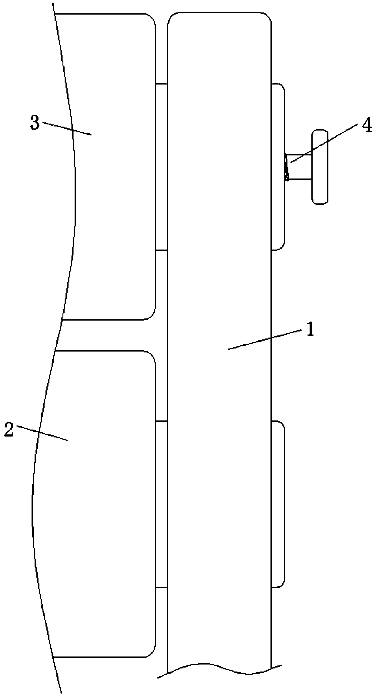
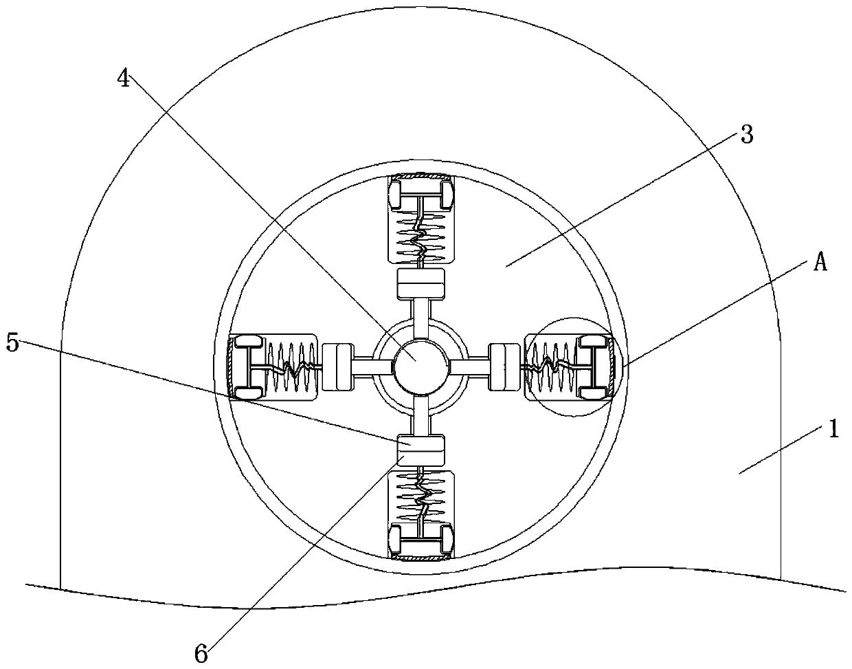
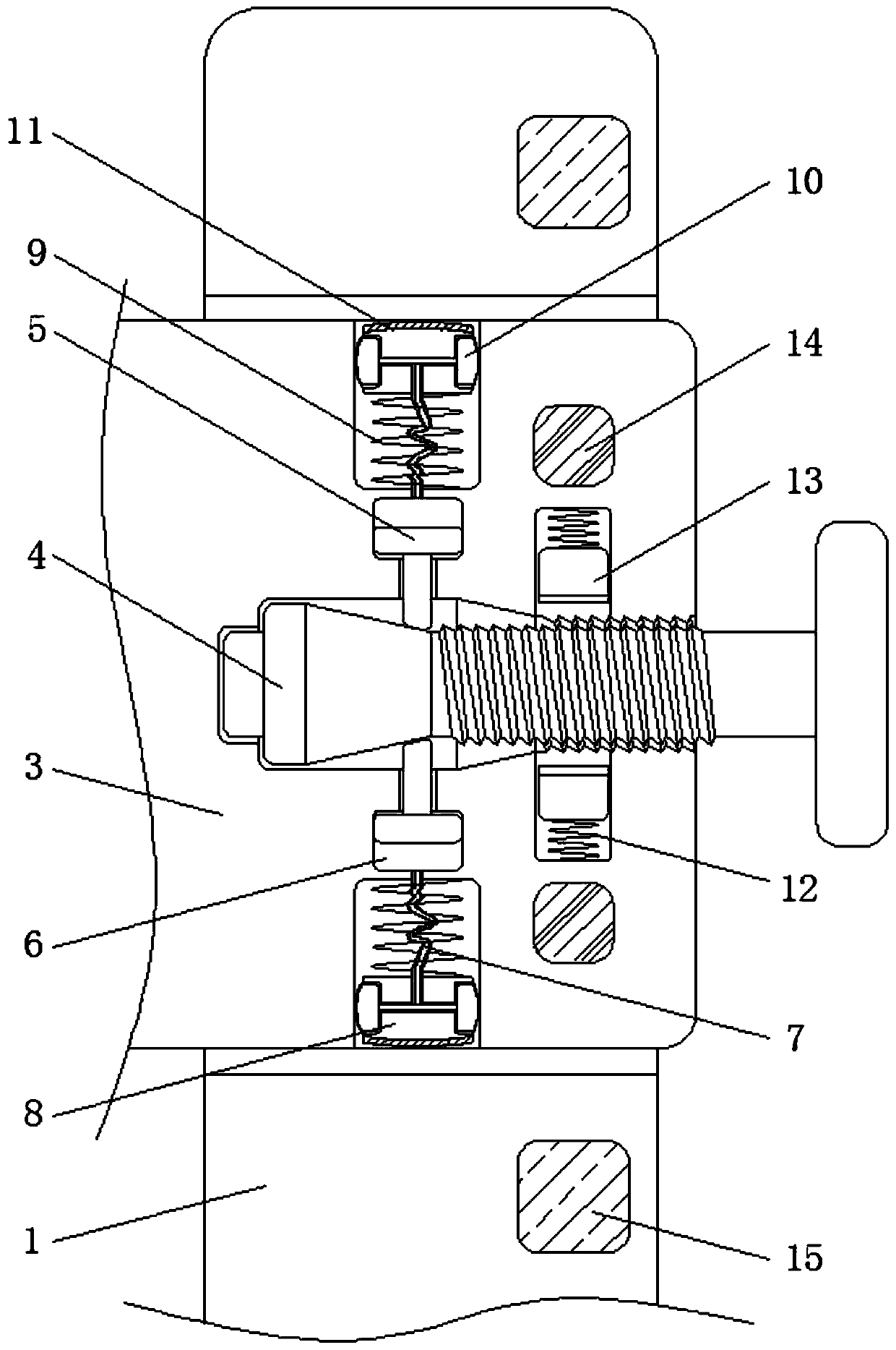
[0021] see Figure 1-5 , a textile washing and drying device, comprising a bracket 1, the bracket 1 plays a supporting role, the material of the bracket 1 is steel material and the top and bottom of the bracket 1 are provided with turning grooves, the size of the driven wheel 2 is the same as that of the driving wheel The size of the wheels 3 is the same and there is no burr on the outside of the driven wheel 2. The bottom of the bracket 1 is connected to the ...


PUM


Abstract

The invention discloses a woven fabric cleaning and drying device and relates to the technical field of textile equipment. The device comprises a support, wherein a driven wheel is rotationally connected to the bottom of the support, a driving wheel is rotationally connected to the top of the support, and a conical screw is in threaded connection with the middle of the driving wheel. According tothe woven fabric cleaning and drying device, through matched use of a slider and a piston rod, when the driving wheel rotates too fast, sliders can be thrown away to the outer side under the action ofcentrifugation force, rubber blocks on the outermost sides of the slider and the inner side of the support are in sliding friction, so that the driving wheel slows down, the driving wheel and woven fabric move together again, and the speed can be regulated and limited by adjusting the conical screw; when the conical screw moves to the front side, the piston rod moves outwards, gas is squeezed into air bags, the air bags swell, friction force between the air bags and the inner wall of the driving wheel is increased, the maximum speed for throwing away is increased, the function of changing theanti-slip interface is achieved, the anti-slip practicability is improved, and the production efficiency is improved.

Description

technical field [0001] The invention relates to the technical field of textile equipment, in particular to a textile cleaning and drying device. Background technique [0002] Fabrics often need to be cleaned during the production process. After cleaning, the fabrics are dried for later storage. During the cleaning and drying process of fabrics, transmission rollers are needed to transport the fabrics. The transmission rollers can It facilitates the movement of the woven fabric, speeds up the cleaning and drying process of the woven fabric, and improves the production efficiency, but the current drive roller still has the following problems during use: [0003] The transmission roller is mainly composed of a driving wheel and a driven wheel. The textile is sandwiched between the driving wheel and the driven wheel. The driving wheel rotates under the drive of the motor, and the driving wheel drives the textile and the driven wheel to rotate. However, the rotation process Amon...

Claims


Application Information

Patent Timeline
Patent Type & Authority Applications(China)
IPC IPC(8): D06B3/10D06B3/34
CPCD06B3/10D06B3/34
Inventor 毛祥溪
Owner 毛祥溪
Learn More