Eureka AIR delivers breakthrough ideas for toughest innovation challenges, trusted by R&D personnel around the world.

In-plane accelerometer and method based on rotary folding beam and nanometer optical resonant cavity

A nano optics and accelerometer technology, applied in the direction of measurement of acceleration, velocity/acceleration/impact measurement, and technology for producing decorative surface effects, etc., can solve the problems of sensitive structural parameters, difficult processing, high cost, etc., and achieve high acceleration - Displacement sensitivity, low mechanical off-axis crosstalk, and resistance to twisting effects

Active Publication Date: 2019-10-15
NORTHWESTERN POLYTECHNICAL UNIV
View PDF9 Cites 11 Cited by
  • Summary
  • Abstract
  • Description
  • Claims
  • Application Information

AI Technical Summary

Problems solved by technology

However, the existing near-field optical resonant structures are usually composed of two groups of movable sub-wavelength gratings and multi-media absorption structures of multiple materials, generally including three or more materials, and contain suspended complex structures, This makes its processing extremely difficult, and the yield rate is not high; in addition, the light intensity acceleration sensitivity of the existing near-field optical resonance structure is below 1.5% / mg, and it is difficult to achieve ultra-high sensitivity and precision acceleration measurement
[0004] For example, the optical nanoelectromechanical displacement sensor proposed by Dustin et al. of Sandia Laboratory in the United States consists of two movable nano-gratings, an air gap and a substrate. The material of the movable nano-grating is amorphous diamond, and the substrate material is silicon dioxide and nitrogen. Another example is the grating group accelerometer proposed by Wang Chen et al. [Chinese Patent No. CN201510036416 patent "grating group micro-mechanical acceleration sensor and its method of measuring acceleration"], which also consists of two groups of movable sub-wavelength gratings, air Gap and substrate composition, the material of the movable grating is single crystal silicon, and the substrate material is silicon dioxide and silicon nitride; Rogers[ROGERS A A A, KEDIA S, SAMSON S, et al.Verification of evanescent coupling from subwavelength grating pairs[J] .Applied Physics B-Lasers and Optics,2011,105(4):833-7.] et al. and Yao et al. of Beijing University of Aeronautics and Astronautics [Yao B Y; Feng L S; Wang X; et al.Design of out-of- plane MOEMS accelerometer with subwavelengthgratings.IEEE Photonics Technology Letters,2014,26(10):1027–30.] Although the micro-optical accelerometer with subwavelength grating group proposed by It is equivalent to a normal diffraction grating, so the light intensity acceleration sensitivity is only 0.0002% / mg and 0.46% / mg, which is far from meeting the needs of ultra-sensitive acceleration measurement
It can be seen that the existing schemes of micro-optical accelerometers based on near-field optical resonators have complex structures or low sensitivity, and because the enhancement of near-field optical resonance is sensitive to structural parameters, the acceleration-sensitive structure has not been optimized. The solution has extremely high requirements on materials and processing technology, and has the disadvantages of high cost and low reliability.

Method used


Image

  • In-plane accelerometer and method based on rotary folding beam and nanometer optical resonant cavity
  • In-plane accelerometer and method based on rotary folding beam and nanometer optical resonant cavity
  • In-plane accelerometer and method based on rotary folding beam and nanometer optical resonant cavity

Examples


Embodiment Construction

[0034] The embodiments described below by referring to the figures are exemplary and are intended to explain the present invention and should not be construed as limiting the present invention.

[0035] In describing the present invention, it should be understood that the terms "center", "longitudinal", "transverse", "length", "width", "thickness", "upper", "lower", "front", " Orientation indicated by rear, left, right, vertical, horizontal, top, bottom, inside, outside, clockwise, counterclockwise, etc. The positional relationship is based on the orientation or positional relationship shown in the drawings, which is only for the convenience of describing the present invention and simplifying the description, rather than indicating or implying that the referred device or element must have a specific orientation, be constructed and operated in a specific orientation, Therefore, it should not be construed as limiting the invention.

[0036] The diagrams provided in this embodim...


PUM

PropertyMeasurementUnit
thicknessaaaaaaaaaa
lengthaaaaaaaaaa
lengthaaaaaaaaaa

Abstract

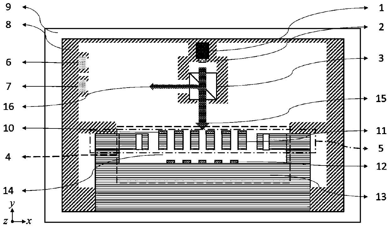
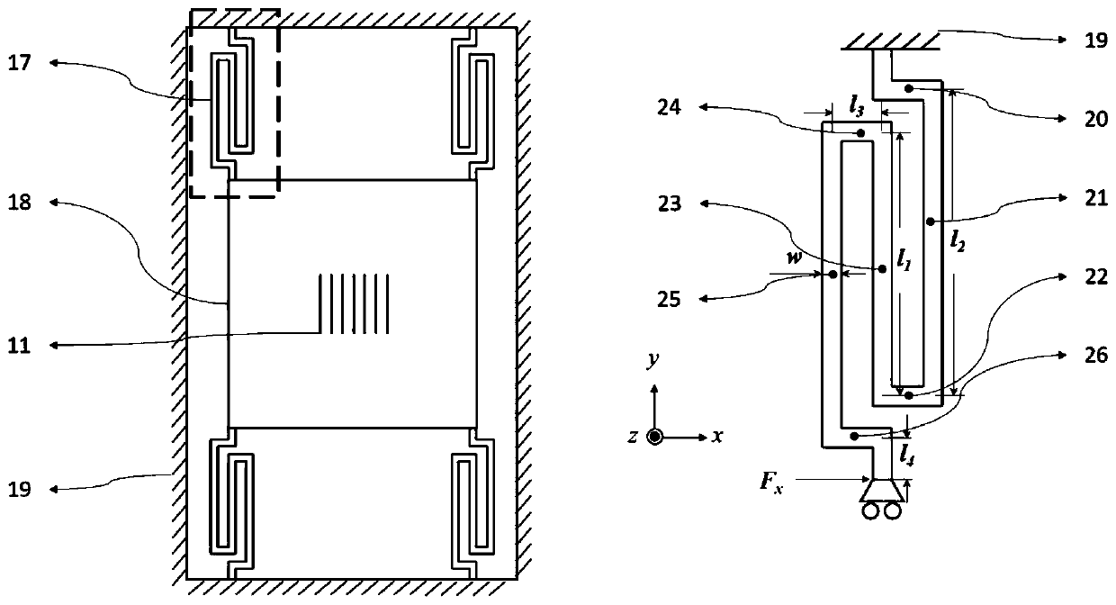
The invention discloses an in-plane accelerometer based on a rotary folding beam and a nanometer optical resonant cavity and a method. The in-plane accelerometer consists of a rotary folding beam-massblock-silicon outer frame acceleration displacement sensitive structure, and a displacement measurement mechanism which consists of the nano optical resonant cavity, a laser, an optical isolator, a beam splitter prism, and two photoelectric detectors. The nanometer optical resonant cavity comprises a sub-wavelength silicon grating covered with a silver film, a layer of air gap and a silicon substrate covered with a silver film. According to the invention, the elastic structure of the rotary folding beam is utilized to achieve high acceleration-acceleration displacement sensitivity and low off-axis crosstalk in-plane acceleration displacement conversion, ultrahigh-sensitivity displacement measurement is achieved through the nanometer optical resonant cavity, and high-measurement-sensitivity in-plane acceleration measurement is achieved through combination of the nanometer optical resonant cavity and the in-plane acceleration displacement conversion; the acceleration displacement sensitive structure and the nanometer optical resonant cavity are both made of a single silicon-on-insulator wafer, so that large-scale, low-cost and high-precision in-plane acceleration measurement can berealized.

Description

technical field [0001] The invention belongs to the field of accelerometers, and in particular relates to an in-plane accelerometer and method based on a rotating folded beam and a nano-optical resonant cavity. Background technique [0002] At present, the measurement principle of micro-optical accelerometers is usually based on the fluctuation of light, that is, the acceleration is converted into a displacement signal through an acceleration-sensitive structure, and then the displacement is measured by using the interference and diffraction effects of the optical signal. However, the displacement measurement based on the fluctuation of light is limited by the wavelength of light and cannot break through the diffraction limit of light. Therefore, the measurement accuracy of displacement and acceleration is limited by the wavelength of light. Although the displacement measurement accuracy can be improved to λ / 100 or even higher through electronic subdivision, modulation and d...

Claims


Application Information

Patent Timeline
Patent Type & Authority Applications(China)
IPC IPC(8): B81B3/00B81C1/00G01P15/093
CPCB81B3/0083B81B3/0035B81C1/00015B81C1/00134G01P15/093B81B2201/0235
Inventor 卢乾波姚远方卫栋白剑王学文
Owner NORTHWESTERN POLYTECHNICAL UNIV
Why Eureka
Eureka Blog
Learn More