A kind of technology method of water-free glass sand molding of anti-gravity pouring investment casting
A technology of anti-gravity pouring and process method, which is applied in the field of water-free glass sand molding of anti-gravity pouring investment castings, can solve the problems of casting scrap, huge pressure difference, equipment damage, etc., to ensure integrity, reduce heat loss, improve The effect of production efficiency
- Summary
- Abstract
- Description
- Claims
- Application Information
AI Technical Summary
Problems solved by technology
Method used
Image
Examples
Embodiment 1
[0049] by size Take the casting as an example. The material of the casting is ZL105. The casting is basin-shaped and has a huge volume. The specific implementation steps of the water-free glass sand molding process are as follows:
[0050] Step 1: Design the gating system according to the characteristics of the casting;
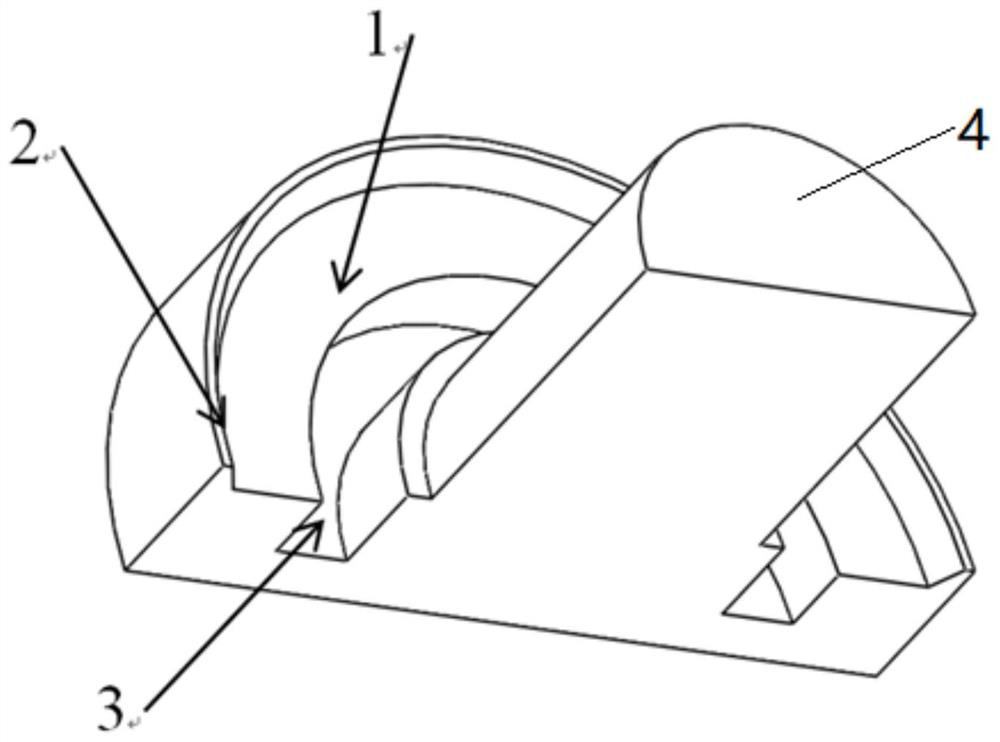
[0051] Step 2: Press the wax mold of the casting, complete the assembly of the casting pouring process plan, and bond the flanging sprue cup to the lower end of the runner. The schematic diagram of the flanging sprue cup is as follows figure 1 As shown, the flanging sprue cup includes: flanging 1, sharp corner removal ring 2 and annular groove 3, flanging 1 is arranged on the outside of cylindrical runner 4, and formed between flanging 1 and cylindrical runner 4 The annular groove 3 is provided with a sharp corner removal ring 2 on the upper part of the flange 1 . The height of the flanging 1 is 10mm.
[0052] Step 3: According to the structural character...
Embodiment 2
[0064] Taking a casting with a size of 295mm×180mm×240mm as an example, the material is ZL114A, the casting is closed in a hemispherical shape, the wall thickness of the whole body is 4mm, and it is hollow. The specific steps of the water-free glass sand molding process are as follows:
[0065] Step 1: Design the gating system according to the characteristics of the casting;
[0066] Step 2: Press the wax mold of the casting, complete the assembly of the casting pouring process plan, and bond the flanging sprue cup to the lower end of the runner. The schematic diagram of the flanging sprue cup is as follows figure 1 As shown, the flanging sprue cup includes: flanging 1, sharp corner removal ring 2 and annular groove 3, flanging 1 is arranged on the outside of cylindrical runner 4, and formed between flanging 1 and cylindrical runner 4 The annular groove 3 is provided with a sharp corner removal ring 2 on the upper part of the flange 1 . The height of the flanging 1 is 10mm. ...
PUM
 Abstract
Description
Claims
Application Information
 - R&D
- Intellectual Property
- Life Sciences
- Materials
- Tech Scout
- Unparalleled Data Quality
- Higher Quality Content
- 60% Fewer Hallucinations
Browse by: Latest US Patents, China's latest patents, Technical Efficacy Thesaurus, Application Domain, Technology Topic, Popular Technical Reports.
© 2025 PatSnap. All rights reserved.Legal|Privacy policy|Modern Slavery Act Transparency Statement|Sitemap|About US| Contact US: help@patsnap.com


