
A formwork bending machine

A technology of a bending machine and a mold base, which is applied in the field of mold base bending and can solve problems such as inconvenience

Active Publication Date: 2021-03-19
NANJING HANXIYUE AUTOMATION TECH CO LTD
View PDF11 Cites 4 Cited by
  • Summary
  • Abstract
  • Description
  • Claims
  • Application Information

AI Technical Summary

Problems solved by technology

The special upper and lower convex and concave dies, unloading plates, positioning parts, etc. corresponding to the size and shape of the stamping parts are all installed on the base plate of the mold base to form a complete set of cold stamping dies; at present, in order to produce more To meet the production and use requirements of different molds, it is necessary to perform bending operations on the local positions of the mold bases. However, some bending equipment cannot meet the bending requirements of different bending arcs for the mold bases, and different equipment is required. It is very inconvenient to bend the mold base, so a mold base bending machine is designed here to solve the above problems

Method used


Image

  • A formwork bending machine
  • A formwork bending machine
  • A formwork bending machine

Examples


Embodiment Construction

[0022] The embodiment of the present application solves the problems raised in the prior art by providing a formwork bending machine; the following will be clearly and completely described in conjunction with the technical solution in the embodiment of the present invention. Obviously, the described embodiment is only It is a part of embodiments of the present invention, but not all embodiments. Based on the embodiments of the present invention, all other embodiments obtained by persons of ordinary skill in the art without making creative efforts belong to the protection scope of the present invention.

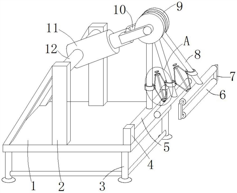
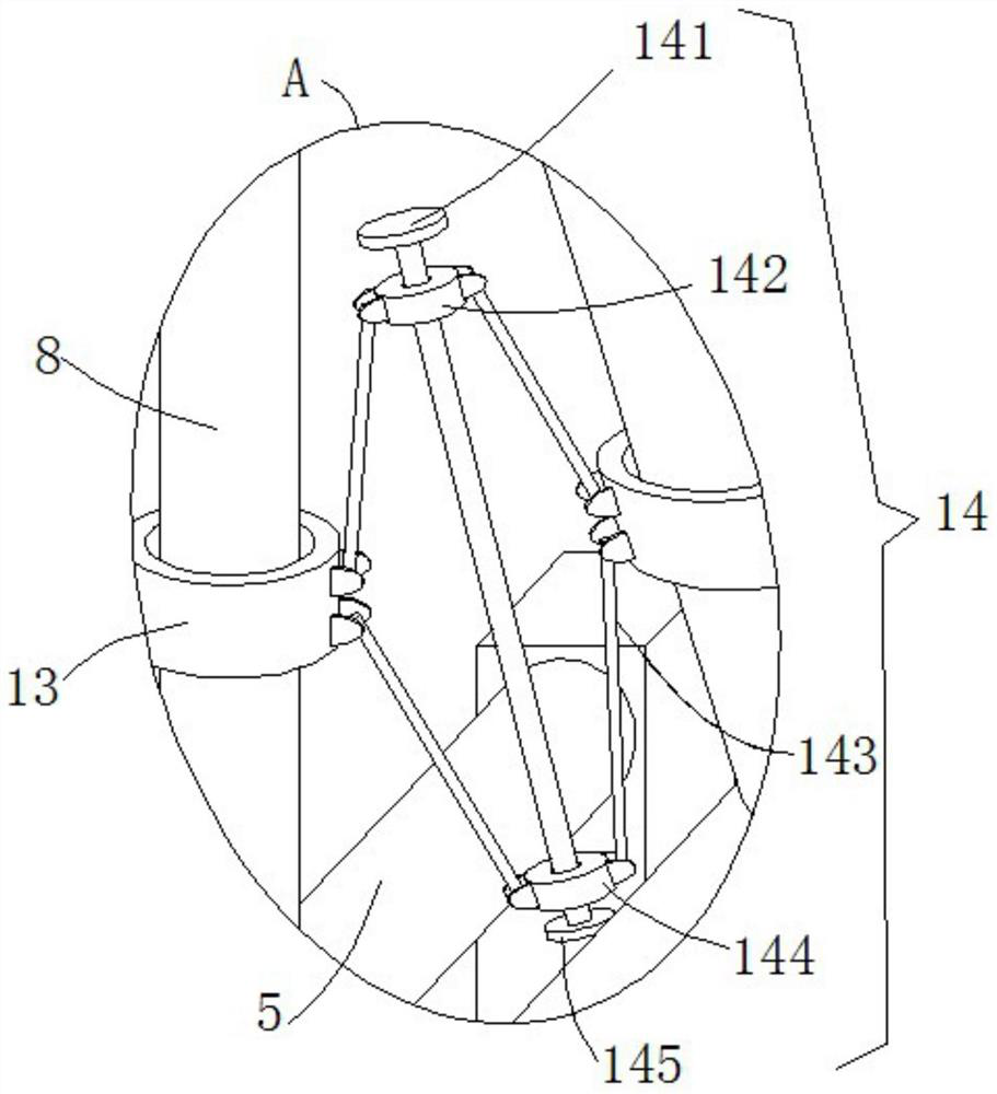
[0023] see Figure 1-3 , this embodiment provides a formwork bending machine, including a bending seat 1 and several adjustment mechanisms 14, the top of the bending seat 1 is vertically provided with support columns 2 on both sides of the front, rear, and two support columns 2 A hydraulic cylinder 11 that can rotate forward and reverse around the middle of the pin shaft 12 i...


PUM

PropertyMeasurementUnit
heightaaaaaaaaaa

Abstract

Disclosed is a mold frame bending machine, comprising a bending base (1) and a plurality of adjusting mechanisms (14), wherein the front side and the rear side of the top end face of the bending base are respectively vertically provided with a supporting stand column (2); the tip end of a hydraulic cylinder (11) is rotatably provided with an I-shaped wheel (9) in a hinged manner by means of a connecting frame (10); a plurality of sliding blocks (81) are slidably clamped between two annular sliding grooves (91) formed in the inner side of the I-shaped wheel; the outer wall of each sliding block is provided with an adjustment rod (8) in a welded manner in the radial direction of the I-shaped wheel; the outer wall of each adjustment rod is slidably sheathed in a hollow sleeve (13); each adjusting mechanism is located at a position between every two adjacent hollow sleeves; a bending guide rod (5) that is distributed at the front and back is welded to the bottom end of each adjustment rod; the front end and the rear end of the bending guide rod at the far left are rotatably arranged on the right side of the top end face of the bending base by means of a hinge frame (4); the front end and the rear end of the bending guide rod at the far right are respectively provided with a hanging rod (7) in a perpendicular manner; and a rolling guide rod (6) is rotatably arranged between the side walls of the bottom ends of the two hanging rods. The mold frame bending machine facilitates the achievement of the bending operation on mold frames with various bending requirements.

Description

technical field [0001] The invention relates to the related technical field of formwork bending, in particular to a formwork bending machine. Background technique [0002] Mold base, usually refers to the general complete set of basic parts of cold stamping die, including upper and lower base plates, guide pillars, guide sleeves, etc. The special upper and lower convex and concave dies, unloading plates, positioning parts, etc. corresponding to the size and shape of the stamping parts are all installed on the base plate of the mold base to form a complete set of cold stamping dies; at present, in order to produce more To meet the production and use requirements of different molds, it is necessary to perform bending operations on the local positions of the mold bases. However, some bending equipment cannot meet the bending requirements of different bending arcs for the mold bases, and different equipment is required. It is very inconvenient to bend the mold base, so a mold b...

Claims


Application Information

Patent Timeline
Patent Type & Authority Patents(China)
IPC IPC(8): B21D7/16
CPCB21D7/16
Inventor 冯亮卫智
Owner NANJING HANXIYUE AUTOMATION TECH CO LTD
Learn More