Fluorescence detector

A technology for fluorescence detectors and light detectors, which is applied in the field of fluorescence detectors, can solve the problems of high price of photodiodes, very high requirements for installation angle and dimensional accuracy of beam splitters, and achieve the goal of reducing design difficulty, reducing material costs, and reducing costs Effect

Pending Publication Date: 2019-10-11
EUROIMMUN MEDICAL DIAGNOSTICS (CHINA) CO LTD
View PDF0 Cites 0 Cited by
  • Summary
  • Abstract
  • Description
  • Claims
  • Application Information

AI Technical Summary

Problems solved by technology

However, prior art closed-loop control solutions have many disadvantages
For example, the photodiode used as a light sensor is expensive; the installation angle and dimensional accuracy of the beam splitter in the main optical path are very high

Method used


Image

  • Fluorescence detector
  • Fluorescence detector
  • Fluorescence detector

Examples


Embodiment Construction

[0027] In order to make the purpose, technical solutions and advantages of the embodiments of the present invention clearer, the technical solutions in the embodiments of the present invention will be clearly and completely described below in conjunction with the drawings in the embodiments of the present invention. Obviously, the described embodiments It is a part of embodiments of the present invention, but not all embodiments. Based on the embodiments of the present invention, all other embodiments obtained by persons of ordinary skill in the art without making creative efforts belong to the protection scope of the present invention.

[0028] In the following detailed description, reference is made to the accompanying drawings which are included in the specification and which illustrate specific embodiments of the application and which are included in this application. In the drawings, like reference numerals describe substantially similar components in different views. Va...


PUM


Abstract

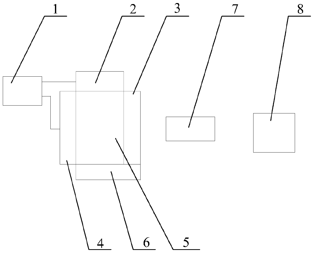
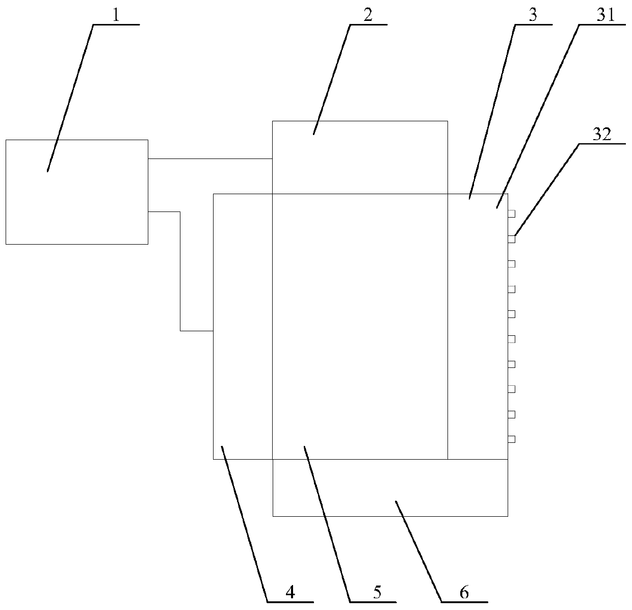
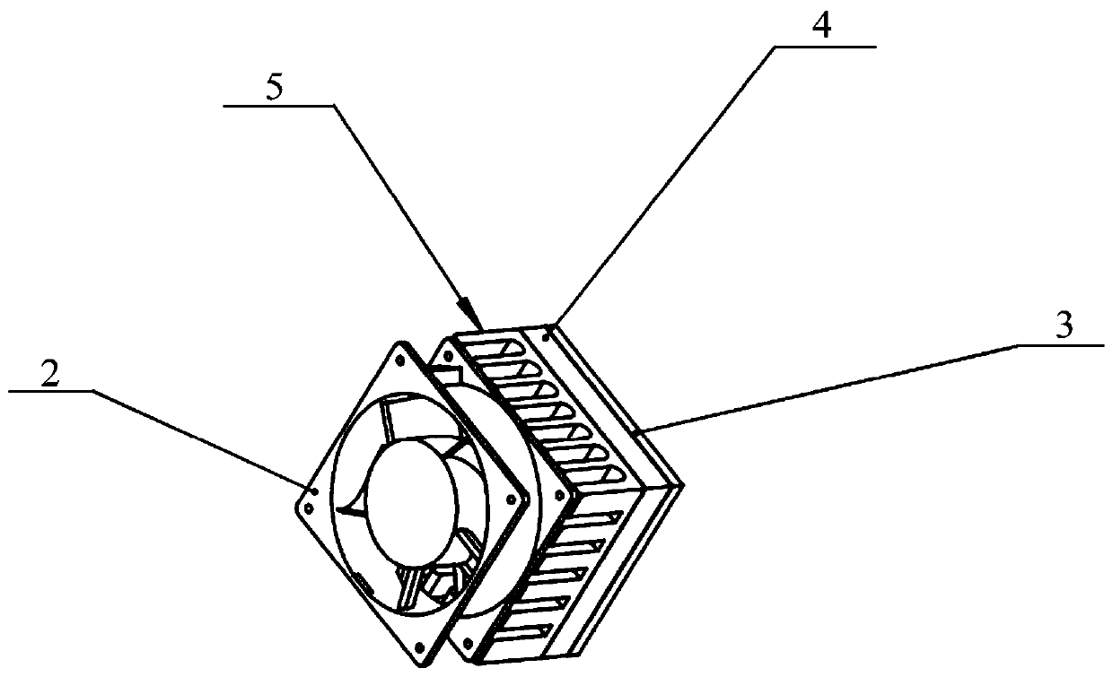
The invention relates to the field of medical device technology, and particularly relates to a fluorescence detector. The fluorescence detector comprises an LED (Light-emitting Diode) component configured for radiating exciting light to a product under test, a photodetector configured for receiving the fluorescence from the product under test, a controller configured for controlling the power fordriving the LED component, a temperature sensor which is connected with the controller and configured for detecting the temperature of the LED component, and a temperature control component which is connected with the controller and configured for adjusting the temperature of the LED component. The fluorescence detector provided by the invention adopts the temperature sensor to replace the photodetector; and thus, the material cost, the design difficulty of the closed-loop feedback control, and the installation dimension requirement of the device are reduced.

Description

technical field [0001] The invention relates to the technical field of medical devices, in particular to a fluorescence detector. Background technique [0002] Fluorescence detectors are a commonly used instrument in the IVD industry. The fluorescence detector irradiates the sample to be tested by exciting the light source, and the sample to be tested is excited to emit fluorescence, and the sample to be tested is detected by measuring the fluorescence intensity. In this process, in order to ensure the stability of the stimulated emission of fluorescence of the sample to be tested, it is necessary to keep the output power of the excitation light stable. At the same time, in order to avoid the quenching of the test product caused by turning on the excitation light source for too long, the excitation light source cannot be turned on continuously for a long time. Therefore, the excitation light source of the fluorescence detector needs to reach a steady state of light output ...

Claims


Application Information

Patent Timeline
Patent Type & Authority Applications(China)
IPC IPC(8): G01N21/64G05D23/20
CPCG01N21/645G01N2021/6463G05D23/20
Inventor 李川王晶马楠
Owner EUROIMMUN MEDICAL DIAGNOSTICS (CHINA) CO LTD
Why Eureka
Try Eureka