
Water-cooled drum brake

A water-cooled, drum-type technology, used in vehicle parts, cooling brakes, brakes, etc., can solve the problems of brake ablation, brake performance decline, and high thermal stress of brake drum heating, to increase the contact area and facilitate the liquid Volume, good heat dissipation effect

Inactive Publication Date: 2019-10-11
高邮市宏生制动器厂
View PDF0 Cites 0 Cited by
  • Summary
  • Abstract
  • Description
  • Claims
  • Application Information

AI Technical Summary

Problems solved by technology

[0002] Drum brakes use the brake transmission mechanism to make the brake shoe press the brake friction plate against the inner side of the brake drum, thereby generating braking force, decelerating the wheel or stopping within the shortest distance as required to ensure driving safety, and Ensure that the car is parked reliably and cannot slide automatically. The existing drum brakes will cause the braking performance to decline and the brakes will be slightly ablated during continuous operation. The excessive heating of the brake drum will lead to high thermal stress and a decrease in braking strength. and so on; when the above situation occurs, the drum brake cannot effectively brake the vehicle quickly and effectively. Now in order to reduce the above risks, a cooling device is usually used to cool the working drum brake. The cooling device usually used The method is to use water cooling to cool the brakes. During cooling, the brakes are cooled by continuously dripping water to the outside of the brake drum. Water tanks must be used to store water in water cooling, but the volume of the water tank is limited. The brake drum rotates with the wheels. The water droplets on the surface of the brake drum will be thrown away by the centrifugal force of the brake drum, which is inconvenient for the recovery and recycling of water droplets, and the water droplets dripping on the road in winter will freeze, which will seriously affect the driving safety of subsequent vehicles. Therefore, a Water-cooled drum brakes

Method used

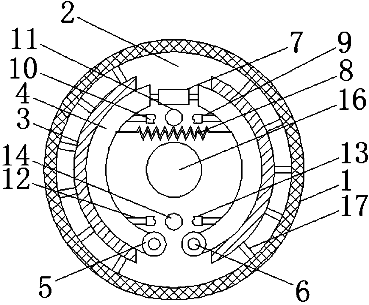
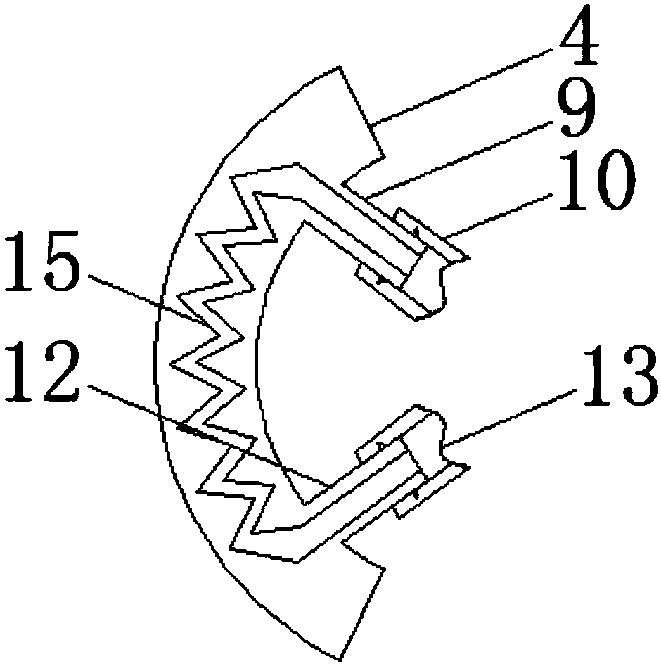
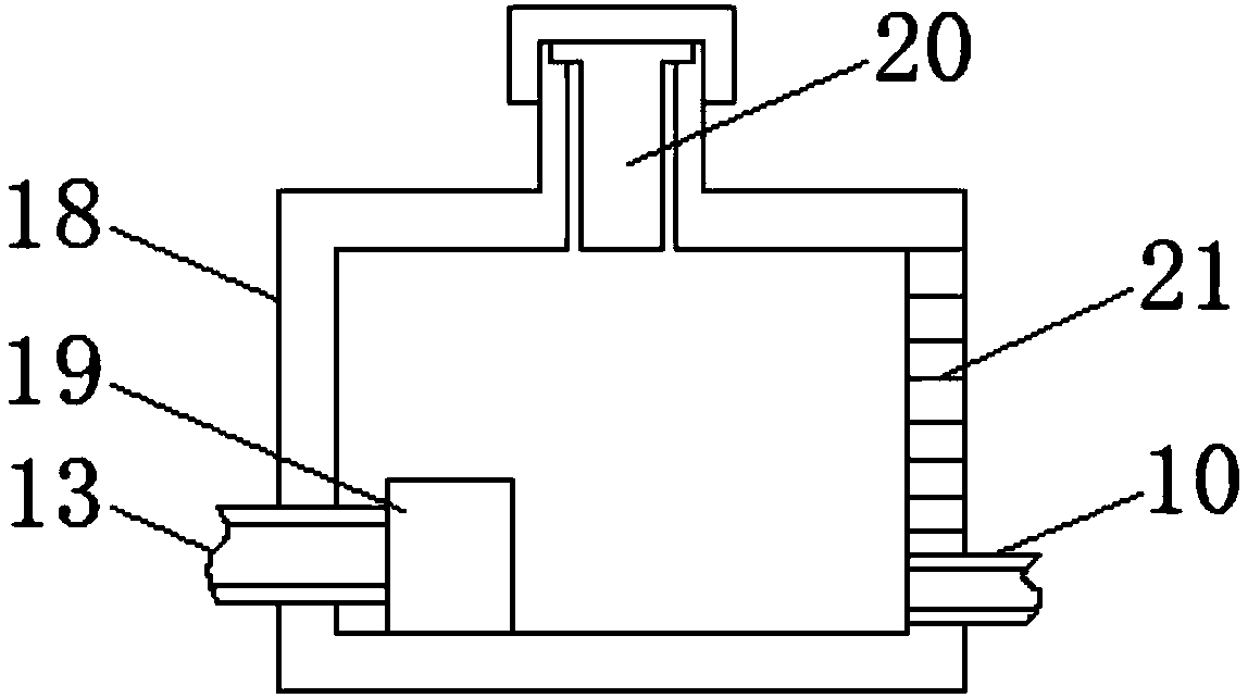

Image

  • Water-cooled drum brake
  • Water-cooled drum brake
  • Water-cooled drum brake

Examples


Embodiment Construction

[0015] The following will clearly and completely describe the technical solutions in the embodiments of the present invention with reference to the accompanying drawings in the embodiments of the present invention. Obviously, the described embodiments are only some, not all, embodiments of the present invention. Based on the embodiments of the present invention, all other embodiments obtained by persons of ordinary skill in the art without making creative efforts belong to the protection scope of the present invention.

[0016] see Figure 1-3 , the present invention provides a technical solution: a water-cooled drum brake, including a brake drum 1, the front side of the brake drum 1 is provided with a fixed plate 2, and the inner cavity of the brake drum 1 is symmetrically provided with two sets of friction blocks 3, The adjacent surfaces of the two groups of friction blocks 3 are all movable with brake shoes 4, the bottom of the brake shoes 4 is provided with a positioning s...


PUM


Abstract

The invention discloses a water-cooled drum brake in the technical field of drum brakes. The water-cooled drum brake includes a brake drum; a fixation plate is movably disposed on the front side of the brake drum; the inner cavity of the brake drum is symmetrically provided with two sets of friction blocks, and adjacent surfaces of the two sets of the friction blocks are movably provided with brake shoes; a brake pump is disposed at the top of the adjacent surface of the brake shoes; a water passage is disposed in the inner cavities of the brake shoes; a water tank is connected to the other end of a water outlet pipe; a water pump is disposed at the bottom of the inner cavity of the water tank; the water tank is filled with cooling water, and the cooling water works through the water pumpand is sent into the inner cavity of the water passage through a water inlet pipe to cool the brake shoes; the saw-toothed water passage increases the contact area between liquid and the friction blocks, which provides a better heat dissipation function; cooling fins play roles of heat conduction and heat dissipation, and the cooling fins play a role of supporting the friction blocks; existence ofheat dissipation holes facilitates circulation of a gas; and the existence of a scale line facilitates observation of the volume of the liquid inside the inner cavity of the water tank.

Description

technical field [0001] The invention relates to the technical field of drum brakes, in particular to a water-cooled drum brake. Background technique [0002] Drum brakes use the brake transmission mechanism to make the brake shoe press the brake friction plate against the inner side of the brake drum, thereby generating braking force, decelerating the wheel or stopping within the shortest distance as required to ensure driving safety, and Ensure that the car is parked reliably and cannot slide automatically. The existing drum brakes will cause the braking performance to decline and the brakes will be slightly ablated during continuous operation. The excessive heating of the brake drum will lead to high thermal stress and a decrease in braking strength. and so on; when the above situation occurs, the drum brake cannot effectively brake the vehicle quickly and effectively. Now in order to reduce the above risks, a cooling device is usually used to cool the working drum brake. ...

Claims


Application Information

Patent Timeline
IPC IPC(8): B60T5/00
CPCB60T5/00
Inventor 袁加林
Owner 高邮市宏生制动器厂
Learn More