
A sparse wireless energy transmission trm design method and structure

A technology of wireless energy transmission and design method, applied in the direction of design optimization/simulation, can solve the problems of limited flexibility of sparse array, inability to apply field distribution design, inability to meet energy transmission efficiency, etc., to achieve efficient and accurate wireless energy transmission, good The effect of applying value and reducing difficulty

Active Publication Date: 2022-05-03
UNIV OF ELECTRONICS SCI & TECH OF CHINA
View PDF3 Cites 0 Cited by
  • Summary
  • Abstract
  • Description
  • Claims
  • Application Information

AI Technical Summary

Problems solved by technology

The specific performance is as follows: First, the optimization target is limited to the far-field distribution of linear arrays or area arrays, which cannot be applied to the field distribution design in complex energy transmission scenarios such as near-field or scattering environments; second, sparse arrays generally only consider the degree of sidelobe suppression , and does not care about the reduction of gain, so it cannot meet the specified energy transmission efficiency requirements; finally, this technology usually uses fixed structural units as the basic units before and after sparse, which limits the structural flexibility of sparse arrays

Method used


Image

  • A sparse wireless energy transmission trm design method and structure
  • A sparse wireless energy transmission trm design method and structure
  • A sparse wireless energy transmission trm design method and structure

Examples


Embodiment 1

[0080] Embodiment 1. Sparse wireless energy transmission TRM structure and design in free space

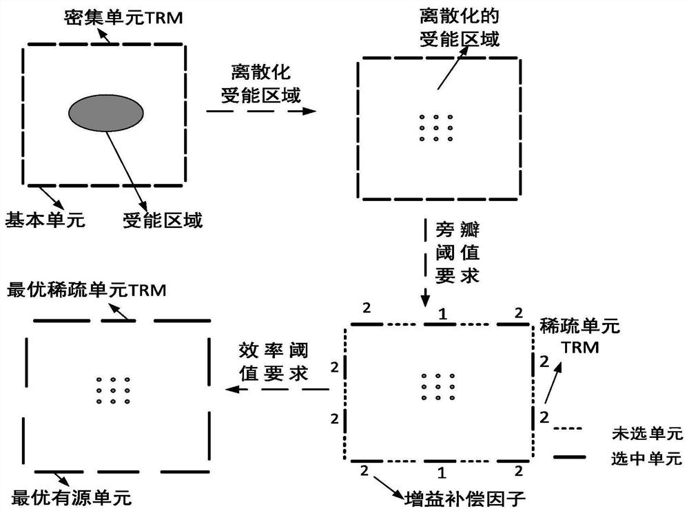
[0081] This embodiment provides a sparse wireless energy transmission TRM design method and structure, the schematic diagram of the design method is as follows figure 1 shown, including the following steps:

[0082] Step 1. Set dense unit TRM and energy transmission index

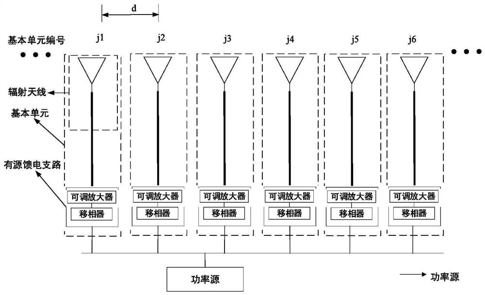
[0083] Set the dense unit TRM as an 8-element line array with equal spacing, and the numbers of the basic units are 1 to 8 from left to right; the powered antenna is 4 equally spaced units located in free space, 500mm away from the TRM array, and the central axis of the transceiver array same as Figure 4 shown. The basic unit of the dense unit TRM is a single-antenna active unit, which is formed by connecting the feed end of a single antenna unit to an active feed branch, such as Figure 5 shown. The transmitting and receiving antenna units are all microstrip patch antennas working at 2.45GHz, and the sp...

Embodiment 2

[0099] Embodiment 2. Sparse wireless energy transmission TRM structure and design in a scattering environment

[0100] Step 1. Set dense unit TRM and energy transmission index

[0101] Set the dense port TRM as an 8-element equidistant line array, the numbers are Ω={1,...,8}, N=8; the energy-receiving areas are four discrete ones located at a distance of 500mm from the TRM line array in the scattering environment Position, that is, the location of the receiving unit; the scatterers are six metal cylinders with a height of 50mm and a spacing of 110mm, located between the transceiver arrays and 200mm away from the normal direction of the TRM line array, such as Figure 9 shown. The basic unit of the dense unit TRM is a single-antenna active unit, which is formed by connecting the feed end of a single antenna to an active feed branch, such as Figure 5 shown. The transmitting and receiving antenna units are all microstrip patch antennas working at 2.45GHz, and the specific par...


PUM


Abstract

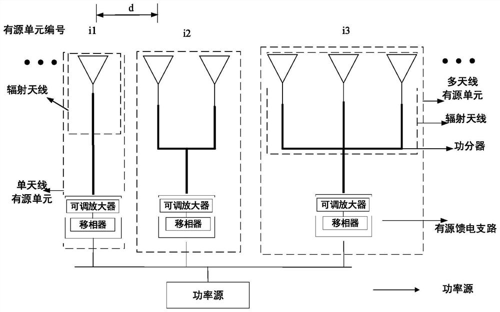
The invention discloses a design method and structure of a sparse wireless energy transmission time inversion mirror, belonging to the technical field of electromagnetic wave wireless energy transmission. The method of the present invention includes the following steps: setting a discretized energy receiving area and a dense unit TRM composed of basic units, and determining the energy transmission index; based on the channel parameters of the dense unit TRM, determining the optimal active unit position, number and The gain compensation factor meets the side lobe threshold index; according to the characteristics of the selected active unit, a sparse active unit TRM is designed to meet the efficiency threshold index. The structural feature of the sparse TRM obtained by using the method of the present invention is that the aperture size of the active unit is an integral multiple of the basic unit, which can be conveniently realized by forming an array of the basic unit. The invention can solve the problems of excessive number of wireless energy transmission TRM active units, complicated power feeding and high system cost, and realizes the sparse design of TRM in various environments while meeting the expected energy transmission index.

Description

technical field [0001] The invention belongs to the technical field of electromagnetic wave wireless energy transmission, and in particular relates to a design method and structure of a sparse wireless energy transmission Time Reversal Mirror (Time Reversal Mirror, TRM). Background technique [0002] Wireless Power Transfer (WPT) refers to the wireless transmission of energy from the power source to the load. Compared with the traditional wired energy transmission method, WPT does not require power transmission cables, which is convenient, flexible, and has urgent application needs and broad prospects. Research on WPT has also attracted the attention of the scientific and industrial circles. The existing WPT technologies include magnetic induction technology, magnetic coupling resonance technology, and microwave wireless energy transmission technology. According to the characteristics of various technologies, it has been gradually applied in various applicable scenarios. ...

Claims


Application Information

Patent Timeline
Patent Type & Authority Patents(China)
IPC IPC(8): G06F30/20
CPCG06F30/20
Inventor 包金龙赵德双王秉中
Owner UNIV OF ELECTRONICS SCI & TECH OF CHINA
Learn More