Hollow rock sample radial seepage test device and test method based on acoustic emission technique

An acoustic emission technology and a test device technology, which are applied in the field of radial seepage test devices for hollow rock samples, can solve the problem that the application of acoustic emission technology is not considered, the water inrush accident from the roof and floor of underground mines is difficult to prevent, and the structural instability of the rock mass cannot be revealed. Problems such as the internal mechanism of water inrush disaster of damaged roof and floor

Active Publication Date: 2019-10-08
CHINA UNIV OF MINING & TECH
View PDF21 Cites 6 Cited by
  • Summary
  • Abstract
  • Description
  • Claims
  • Application Information

AI Technical Summary

Problems solved by technology

[0004] Water inrush in underground roadway can be similarly simulated as the radial seepage model of hollow rock sample. The radial seepage test of hollow rock sample has been designed with relatively mature test equipment and scheme, but the condition of two-way osmotic pressure is not considered
In recent years, acoustic emission technology has been widely used in rock mechanics tests to study the evolution of rock damage state and the development of rock internal cracks. Experts at home and abroad have made many remarkable achievements in the application of acoustic emission technology, but there is Considering the application of acoustic emission technology in the field of seepage research
Under engineering conditions with high osmotic pressure and high ground stress, a single test method cannot reveal the internal mechanism of structural instability failure of rock mass and water inrush disasters of roof and floor
At present, there are still many deficiencies in the research on rock mass instability mechanism and water inrush mechanism, and it is difficult to prevent and control water inrush accidents on the roof and floor of underground mines.

Method used


Image

  • Hollow rock sample radial seepage test device and test method based on acoustic emission technique
  • Hollow rock sample radial seepage test device and test method based on acoustic emission technique

Examples


Embodiment Construction

[0034] The present invention will be further described below in conjunction with the embodiment in the accompanying drawings:

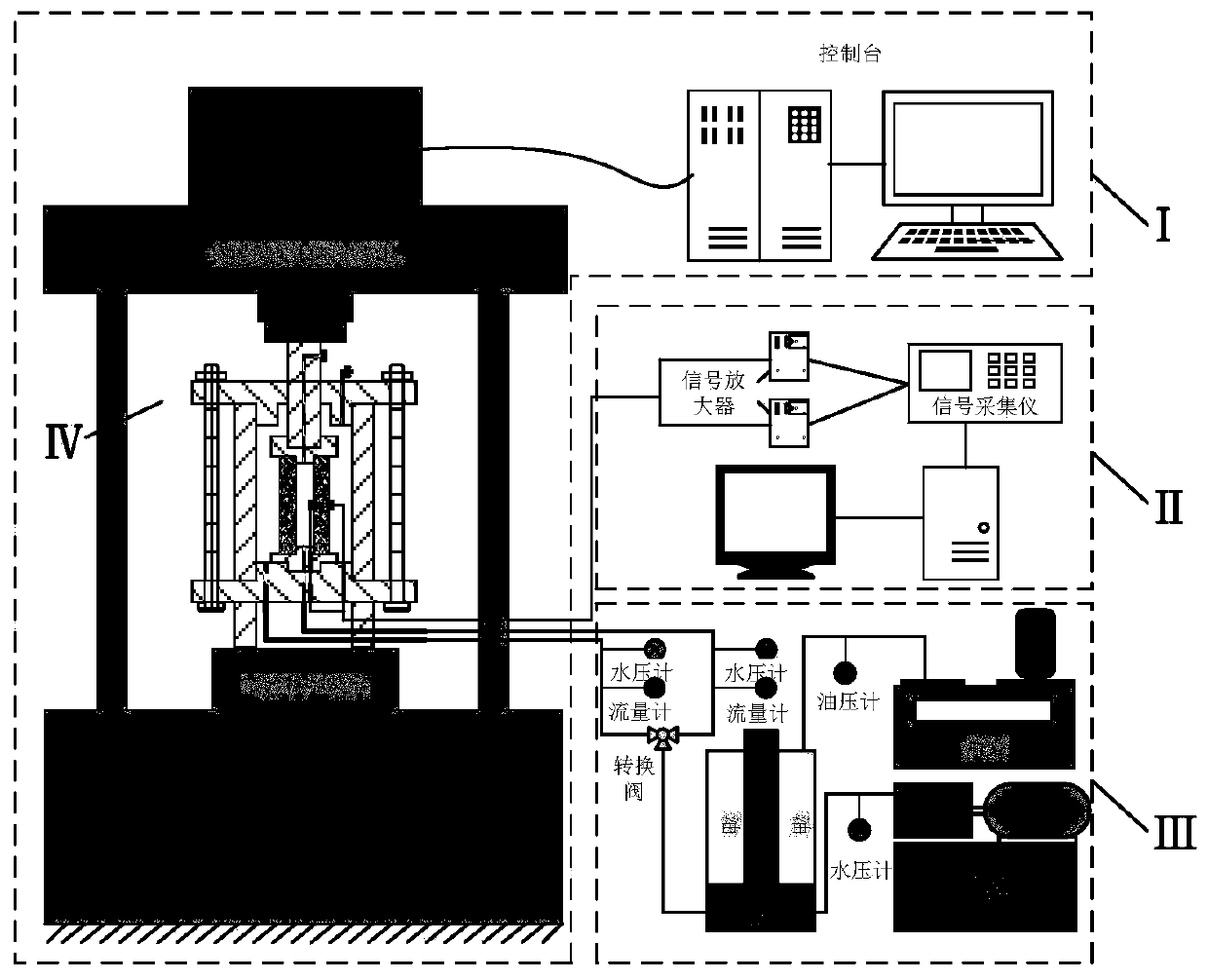
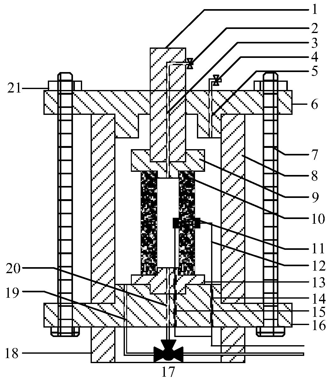
[0035] Such as Figure 1-2As shown, the hollow rock sample radial seepage test device based on acoustic emission technology of the present invention is mainly composed of axial loading system I, radial seepage system IV, hydraulic supply system III and acoustic emission system II. The loading system I includes a testing machine and a control console for controlling the testing machine. The radial seepage system IV is set on the loading table of the testing machine of the axial loading system I. The acoustic emission system II and the hydraulic supply system III are located in the radial direction. One side of the seepage system IV is connected to the radial seepage system IV through signal lines and pipelines respectively; the acoustic emission system II includes a signal amplifier, a signal collector and a computer connected to the probe 11 in turn b...


PUM


Abstract

The invention discloses a hollow rock sample radial seepage test device and test method based on acoustic emission technique. The test device is composed of an axial loading system, an acoustic emission system, a water pressure supply system and a radial seepage system; the axial loading system is acted on the radial seepage system, the water pressure supply system providing periphery water pressure and internal periphery water pressure for the hollow rock sample; the acoustic emission system is used for researching damage and crack extension rule in the rock sample damage process; when the device is specifically applied, the radial seepage test of the hollow rock sample with different bonding strengths can be developed, and the damage mechanism and radial seepage rule under the stress-seepage coupling effect can be researched. The invention further provides a hollow rock sample radial seepage test method based on the acoustic emission technique, specifically, the axial loading systemis used as a power source and the water supply system to perform acoustic emission test and radial seepage test for the water pressure source, and the test device has the advantages of being multifunctional and stable.

Description

technical field [0001] The invention relates to a radial seepage test device and a test method, in particular to a hollow rock sample radial seepage test device and a test method based on acoustic emission technology suitable for research on hollow rock sample radial seepage and damage mechanism. Background technique [0002] The rapid development of my country's economy has a strong demand for mineral resources. Under the condition that the shallow resources are gradually exhausted, in order to meet the needs of the rapid development of the national economy for mineral resources, the mining and utilization of mineral resources are gradually developing to the deep. Due to the complex hydrogeological conditions of most mines in my country, a large number of mineral resources cannot be exploited normally due to the impact of water inrush disasters. In the mining process of deep underground mineral resources, underground roadways and stopes are subjected to high osmotic pressur...

Claims


Application Information

Patent Timeline
Patent Type & Authority Applications(China)
IPC IPC(8): G01N3/12G01N15/08G01N29/14
CPCG01N3/12G01N15/0826G01N29/14G01N2203/0003G01N2203/0019G01N2203/0048G01N2203/0066G01N2291/023G01N2291/0289
Inventor 马丹王佳军张吉雄马晓桐黄艳利周子龙
Owner CHINA UNIV OF MINING & TECH
Why Eureka
Try Eureka