Phosphated residue treatment system and technology in wire surface treatment production line

Inactive Publication Date: 2019-10-08
BAOSTEEL GRP NANTONG WIRE PROD +1
View PDF4 Cites 1 Cited by
  • Summary
  • Abstract
  • Description
  • Claims
  • Application Information

AI Technical Summary

Problems solved by technology

[0002] On the phosphating unit for the surface treatment of metal wires, the heating temperature of the phosphating solution in the phosphating tank is generally controlled above 75°C. The phosphating solution used is generally zinc-based phosphating solution or manganese-based phosphating solution. After reacting with Fe It will produce insoluble iron phosphate and other insoluble salts - called phosphating slag, which will be deposited at the bottom of the tank. If it is not removed in time, it will affect the phosphating effect of metal materials
[0003] At present, some enterprises adopt the method of sedimentation outside the tank, that is, a phosphating solution sedimentation tank is set up outside the tank, and the phosphating solution in the tank is regularly discharged into the sedimentation tank. After a period of precipitation, the clarified phosphating solution is washed again. It can be reused in the phosphating tank, and then the phosphating slag at the bottom is bagged and transported to a special treatment plant. Although this form can realize the treatment of phosphating slag in the phosphating tank, it must be shut down for treatment, and each treatment requires Manually dig out the mixture in the phosphating tank and send it to the sedimentation tank, and then the phosphating slag treated in this way also contains a large amount of phosphating solution, which causes a certain waste and increases the treatment cost of the phosphating slag

Method used


Image

  • Phosphated residue treatment system and technology in wire surface treatment production line

Examples


Embodiment Construction

[0016] Embodiments of the technical solutions of the present invention will be described in detail below in conjunction with the accompanying drawings. The following examples are only used to illustrate the technical solutions of the present invention more clearly, and therefore are only examples, rather than limiting the protection scope of the present invention.

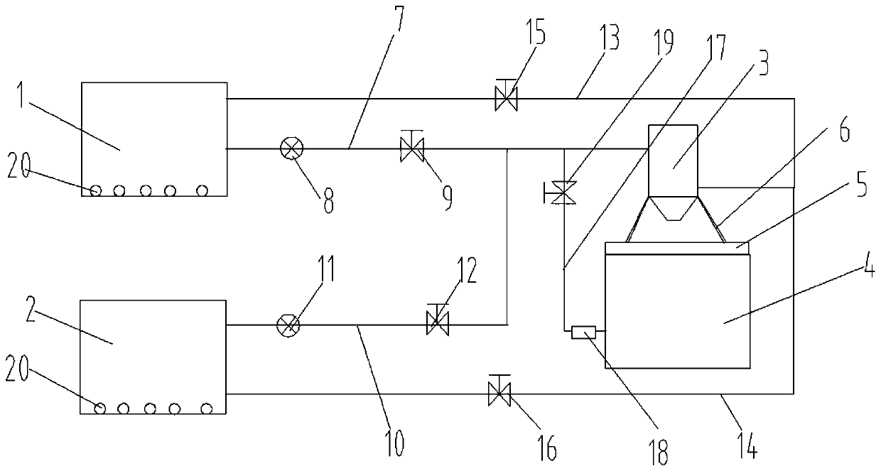
[0017] Such as figure 1 As shown, the phosphating slag treatment system in a wire surface treatment production line disclosed by the present invention includes a first phosphating cylinder 1, a second phosphating cylinder 2, a centrifuge 3 and an emergency pool 4, and the surface of the emergency pool is Covered with a mesh cover 5, the centrifugal separator is installed on the mesh cover through a support frame 6, and the first phosphating cylinder communicates with the inlet of the centrifugal separator through a first pipeline 7, and the first pipeline The first cam pump 8 and the first electromagnetic valve 9 ...


PUM


Abstract

The invention discloses a phosphated residue treatment system in a wire surface treatment production line. The phosphated residue treatment system comprises a first phosphating cylinder, a second phosphating cylinder and a centrifugal separator, the first phosphating cylinder communicates with an inlet of the centrifugal separator through a first pipeline, a first cam pump and a first solenoid valve are mounted on the first pipeline, the second phosphating cylinder communicates with the inlet of the centrifugal separator through a second pipeline, a second cam pump and a second solenoid valveare mounted on the second pipeline, a liquid outlet of the centrifugal separator communicates with the first phosphating cylinder through a third pipeline and communicates with the second phosphatingcylinder through a fourth pipeline, and a third solenoid valve is mounted on the third pipeline, a fourth solenoid valve is mounted on the fourth pipeline, and aeration pipes are mounted in the firstphosphating cylinder and the second phosphating cylinder.

Description

technical field [0001] The invention relates to the field of phosphating slag treatment, in particular to a phosphating slag treatment system and a treatment process in a wire surface treatment production line. Background technique [0002] On the phosphating unit for the surface treatment of metal wires, the heating temperature of the phosphating solution in the phosphating tank is generally controlled above 75°C. The phosphating solution used is generally zinc-based phosphating solution or manganese-based phosphating solution. After reacting with Fe It will produce insoluble ferric phosphate and other insoluble salts - called phosphating slag, which will deposit on the bottom of the tank. If it is not removed in time, it will affect the phosphating effect of metal materials. [0003] At present, some enterprises adopt the method of sedimentation outside the tank, that is, a phosphating solution sedimentation tank is set up outside the tank, and the phosphating solution in ...

Claims


Application Information

Patent Timeline
Patent Type & Authority Applications(China)
IPC IPC(8): C02F1/38
CPCC02F1/38
Inventor 王敏东张军范强谢景明朱从宣
Owner BAOSTEEL GRP NANTONG WIRE PROD
Why Eureka
Try Eureka