Vehicle visor with cosmetic mirror
A technology for sun visors and vanity mirrors, which is applied to sun visor lighting devices, vehicle parts, anti-glare equipment, etc. It can solve the problems of single luminous color, difficulty, and poor aesthetics, and achieve good light uniformity, beautiful appearance, and easy to use. Feel good effect
- Summary
- Abstract
- Description
- Claims
- Application Information
AI Technical Summary
Problems solved by technology
Method used
Image

Examples
Embodiment 1
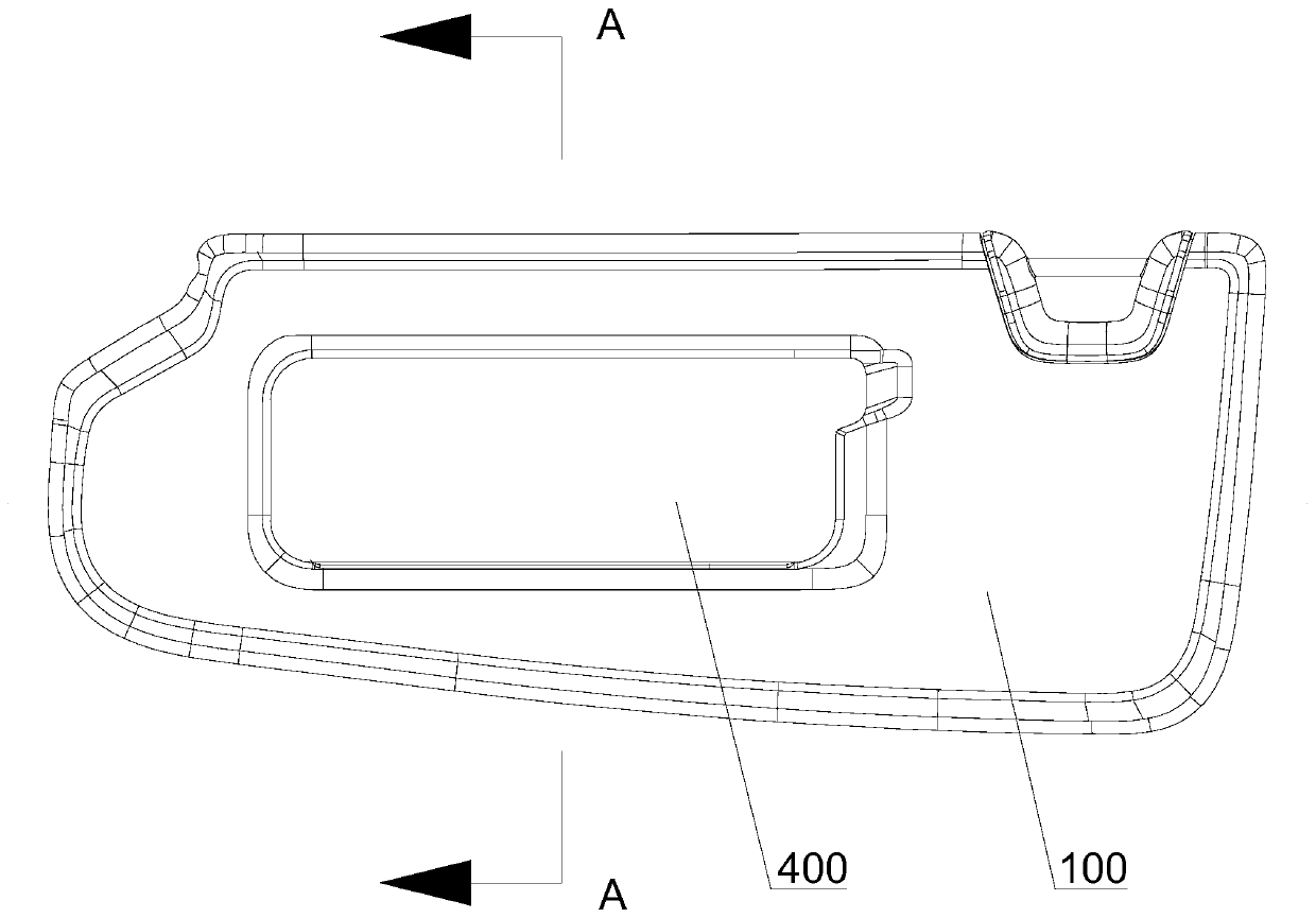
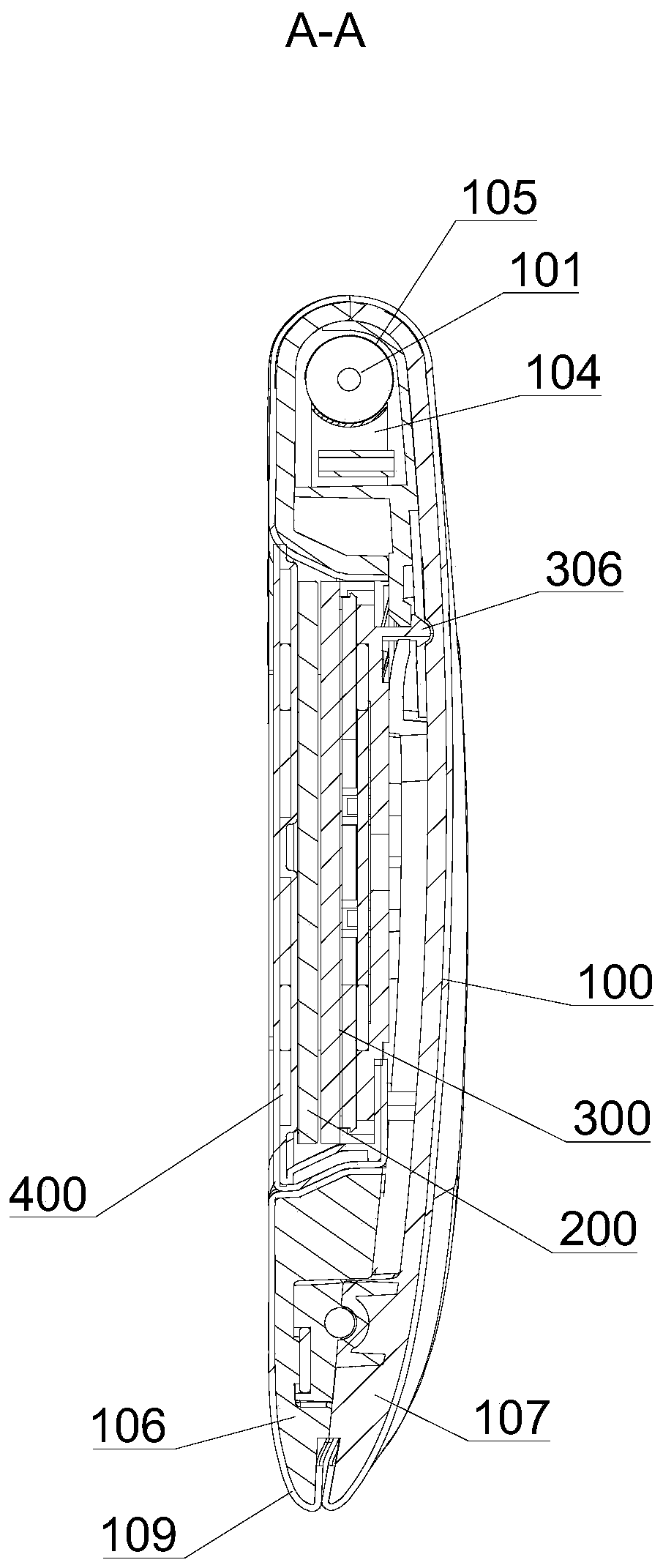
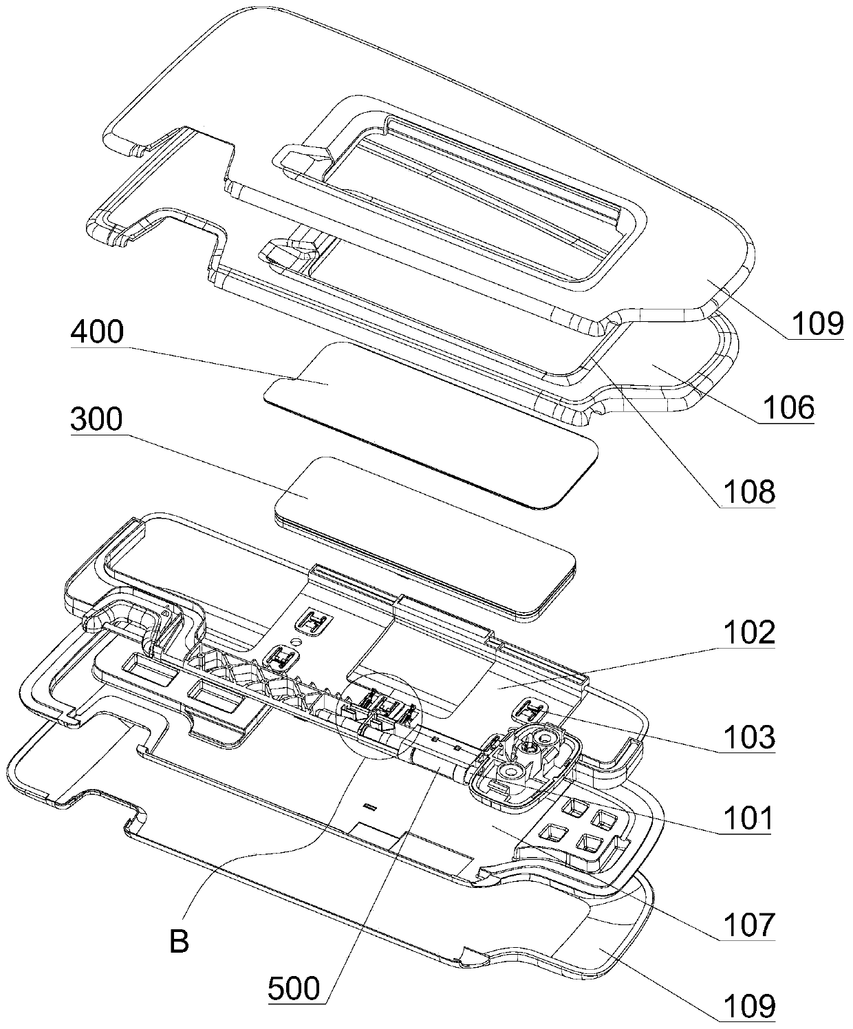
[0032] see Figures 1 to 8 As shown, the present embodiment provides a vehicle sun visor with vanity mirror, which mainly includes a sun visor main body 100 , a mirror 200 , a backlight module 300 and a mirror cover assembly 400 .
[0033] The backlight module 300 includes a substrate 301, a PCB board 302 with LED lights, a light guide plate 303, and a diffuser plate 304 stacked in sequence. Both sides of the light guide plate 303 are provided with reflective films 305, and the diffuser plate 304 is convex on the side facing the substrate 301. There are several clamping posts 306, and the substrate 301 is provided with clamping holes 307 corresponding to the clamping posts 306. The clamping posts 306 pass through the light guide plate 303 and the PCB board 302 and are inserted into the clamping holes 307 to form fixation. The diffusion plate 304 is on the side facing away from the substrate 301. The mirror 200 is bonded with adhesive tape 308, and the edge of the diffusion pla...
Embodiment 2
[0043] Different from Embodiment 1, this embodiment proposes a backlight module 300' with a different structure, please refer to Figures 9 to 11 shown. The backlight module 300' includes a substrate 301', a PCB board 302', a light guide plate 303', and a diffusion plate 304' stacked in sequence. There is a reflective film 305', and a number of clamping posts 306' protrude from the side of the diffuser plate 304' facing the substrate 301'. The substrate 301' is provided with a clamping hole 307' corresponding to the clamping posts 306', and the clamping posts 306' pass through the light guide plate 303 ’, PCB board 302’ and inserted into the card hole 307’ to form a fixation, there is a filling glue 309’ between the PCB board 302’ and the base plate 301’, and a number of inserts protrude from the side of the base plate 301’ facing away from the PCB board 302’ Buckle 310 ′, the framework 102 is provided with a slot 103 corresponding to the buckle 310 ′, and the buckle 310 ′ is...
Embodiment 3
[0046] On the basis of Embodiment 1 or 2, in order to increase the diversity of light sources and improve the controllability of light, a plurality of LED lights of different colors are arranged on the PCB to emit light of various colors. Here, for the backlight module 300' and setting RGBW four-color LEDs on the PCB board 302' as an example, Figure 12 It is a layout diagram of the LED lamp 313' and the light guide plate 303', and the structure of the light guide plate 303' facilitates the light mixing of the four LED lamps 313'. In addition, a touch module is provided on the back of the mirror 200, and the touch module is electrically connected to the PCB board 302' for realizing stepless color change of the light. In particular, the touch module adopts a touch sliding control method, and the two ends of the mirror surface of the mirror 200 are two touch areas 600, such as Figure 13 As shown, corresponding to the adjustment of brightness and color, for example, the upper s...
PUM
 Abstract
Description
Claims
Application Information
 - R&D
- Intellectual Property
- Life Sciences
- Materials
- Tech Scout
- Unparalleled Data Quality
- Higher Quality Content
- 60% Fewer Hallucinations
Browse by: Latest US Patents, China's latest patents, Technical Efficacy Thesaurus, Application Domain, Technology Topic, Popular Technical Reports.
© 2025 PatSnap. All rights reserved.Legal|Privacy policy|Modern Slavery Act Transparency Statement|Sitemap|About US| Contact US: help@patsnap.com