Liquid crystal display device
A technology of liquid crystal display devices and liquid crystal compositions, applied in liquid crystal materials, porphine/acridine porphine, optics, etc., can solve problems such as uneven orientation, increased ion density of voltage retention rate, and white spots, so as to prevent white spots and Reduced effect
- Summary
- Abstract
- Description
- Claims
- Application Information
AI Technical Summary
Problems solved by technology
Method used
Image

Examples
Embodiment 1~5
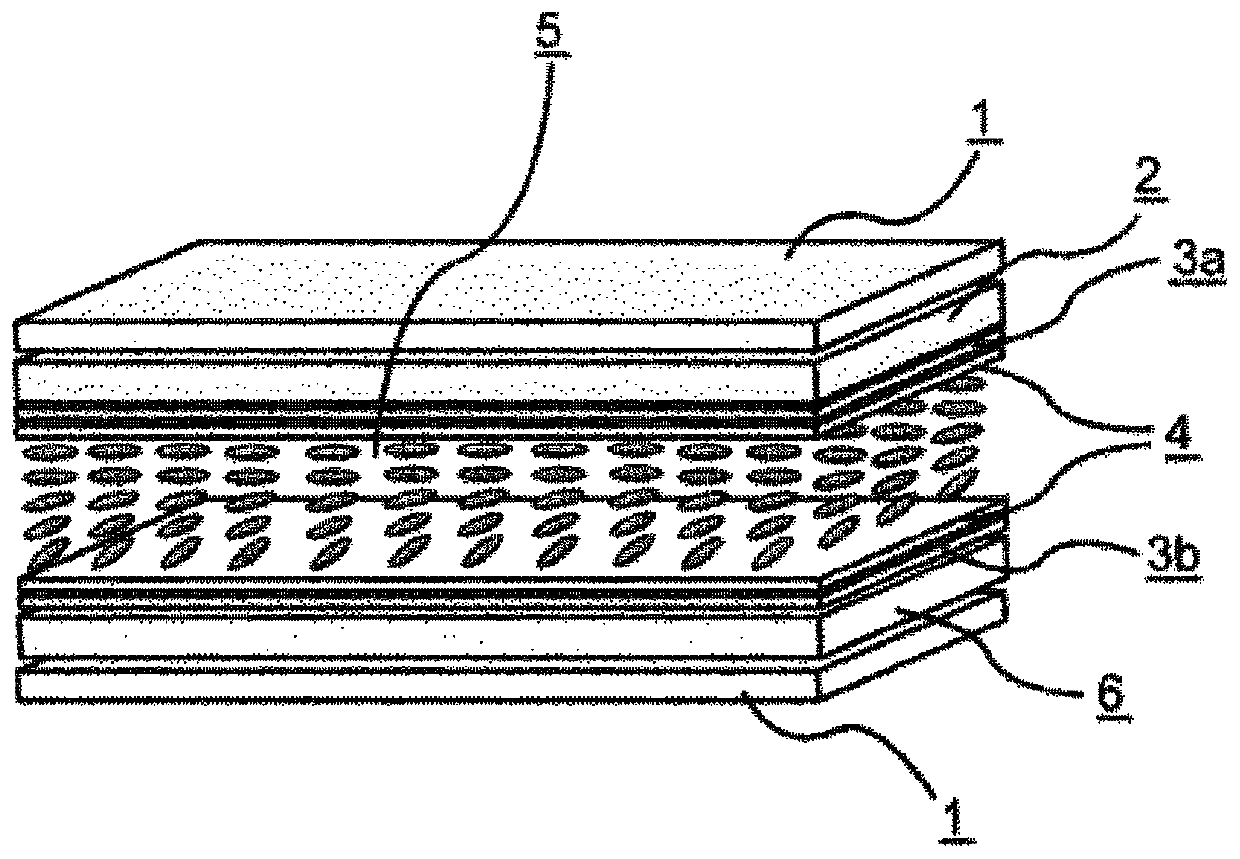
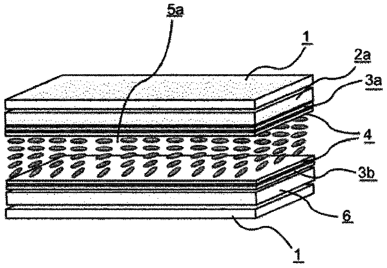
[0410]Fabricate an electrode structure on at least one of the first and second substrates, perform a weak rubbing treatment after forming a horizontally oriented alignment film on the respective opposite sides, and fabricate an IPS unit, sandwiching between the first substrate and the second substrate Liquid crystal composition 1 shown below was used. The physical property values of the liquid crystal composition 1 are shown in the following table. Next, using the color filters 1 to 5 shown in the above table, the liquid crystal display devices of Examples 1 to 5 were fabricated (d gap =4.0 μm, alignment film AL-1051). The VHR of the obtained liquid crystal display device was measured. In addition, burn-in evaluation was performed on the obtained liquid crystal display device. The results are shown in the following tables.
[0411] [Table 11]
[0412] Liquid crystal composition 1
[0413]
[0414] [Table 12]
[0415] Example 1 Example 2 Example 3 ...
Embodiment 6~15
[0419] In the same manner as in Example 1, liquid crystal display devices of Examples 6 to 15 were produced by sandwiching liquid crystal compositions 2 to 3 shown in the following table, and using color filters 1 to 5 shown in the above table, and their VHRs were measured. In addition, this liquid crystal display device was evaluated for burn-in. The results are shown in the following tables.
[0420] [Table 13]
[0421]
[0422] [Table 14]
[0423] Example 6 Example 7 Example 8 Example 9 Example 10 liquid crystal composition Liquid crystal composition 2 Liquid crystal composition 2 Liquid crystal composition 2 Liquid crystal composition 2 Liquid crystal composition 2 color filter color filter 1 color filter 2 color filter 3 color filter 4 color filter 5 VHR 99.4 99.5 99.6 99.5 99.5 burn screen ○ ○ ◎ ◎ ◎
[0424] [Table 15]
[0425] Example 11 Example 12 Example 13 Example 14 E...
Embodiment 16~30
[0428] Liquid crystal display devices of Examples 16 to 30 were produced by sandwiching liquid crystal compositions 4 to 6 shown in the following table in the same manner as in Example 1, and their VHRs were measured using color filters 1 to 5 shown in the above table. In addition, this liquid crystal display device was evaluated for burn-in. The results are shown in the following tables.
[0429] [Table 16]
[0430]
[0431] [Table 17]
[0432] Example 16 Example 17 Example 18 Example 19 Example 20 liquid crystal composition Liquid crystal composition 4 Liquid crystal composition 4 Liquid crystal composition 4 Liquid crystal composition 4 Liquid crystal composition 4 color filter color filter 1 color filter 2 color filter 3 color filter 4 color filter 5 VHR 99.4 99.4 99.6 99.6 99.5 burn screen ○ ○ ◎ ◎ ○
[0433] [Table 18]
[0434] Example 21 Example 22 Example 23 Example 24 Ex...
PUM
| Property | Measurement | Unit |
|---|---|---|
| particle diameter | aaaaa | aaaaa |
Abstract
Description
Claims
Application Information
 - R&D
- Intellectual Property
- Life Sciences
- Materials
- Tech Scout
- Unparalleled Data Quality
- Higher Quality Content
- 60% Fewer Hallucinations
Browse by: Latest US Patents, China's latest patents, Technical Efficacy Thesaurus, Application Domain, Technology Topic, Popular Technical Reports.
© 2025 PatSnap. All rights reserved.Legal|Privacy policy|Modern Slavery Act Transparency Statement|Sitemap|About US| Contact US: help@patsnap.com