A polymer sheet stacking conveying device

A conveying device and polymer technology, applied in the direction of conveyors, transportation and packaging, object stacking, etc., can solve the problems affecting the production efficiency of the assembly line, reducing the speed of stacking plates, etc., to avoid damage to the plates, reduce labor intensity, improve speed effect

Active Publication Date: 2020-10-30
ZHEJIANG FENGBANG MACHINERY TECH CO LTD
View PDF1 Cites 0 Cited by
  • Summary
  • Abstract
  • Description
  • Claims
  • Application Information

AI Technical Summary

Problems solved by technology

However, the plate transfer mechanism in this device needs to be set to move inward or outward driven by the cylinder, so as to complete the stacking or transportation of the plates. It takes time for the plate transfer mechanism to move back and forth, which reduces the speed of stacking plates and affects the production efficiency of the assembly line.

Method used


Image

  • A polymer sheet stacking conveying device
  • A polymer sheet stacking conveying device
  • A polymer sheet stacking conveying device

Examples


specific Embodiment approach 1

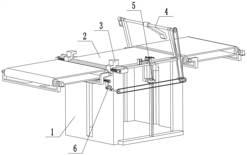
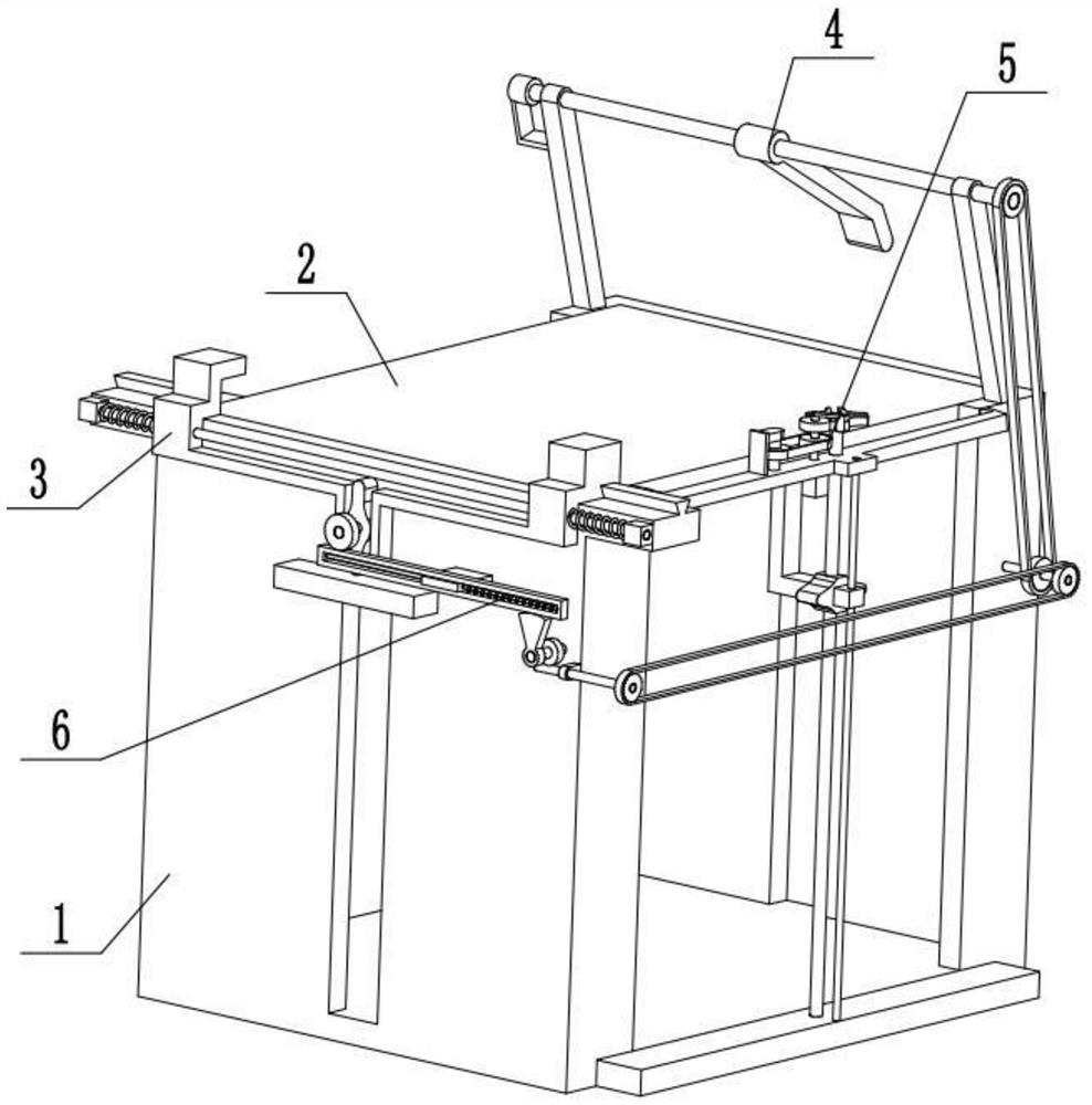
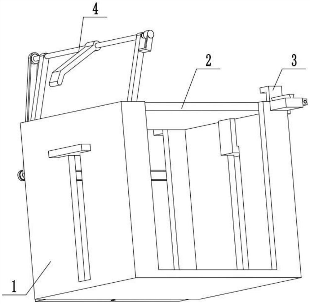
[0028] Combine below Figure 1-11Describe this embodiment, a polymer plate stacking and conveying device, including a plate storage rack 1, a plate support plate 2, a plate limit mechanism 3, a push plate mechanism 4, a support plate control mechanism 5 and a limit adjustment mechanism 6, the The right side of the plate storage frame 1 is provided with an input belt device, the left side of the plate storage frame 1 is provided with an output belt device, the plate pallet 2 is slidingly fitted and connected to the inside of the plate storage frame 1, and the top surface of the plate pallet 2 is connected to the The top surface of the plate storage rack 1, the upper end surface of the input belt device and the upper end surface of the output belt device are all in the same horizontal plane, the plate limit mechanism 3 is arranged on the upper end of the left end of the plate supporting plate 2, and the plate limit mechanism 3 is located at the plate storage Between the frame 1 ...

specific Embodiment approach 2

[0030] Combine below Figure 1-11 To illustrate this embodiment, the plate storage frame 1 includes a bottom frame plate 1-1, a U-shaped frame plate 1-2, a vertical slot 1-3, a rectangular seat 1-4 and a trapezoidal slide rail 1-5; two The U-shaped frame plates 1-2 are symmetrically and fixedly connected on the bottom frame plate 1-1, and a vertical slot 1-3 is arranged in the middle of the two U-shaped frame plates 1-2, and the U-shaped frame plate 1-2 on the left side The upper end of the upper end is fixedly connected with two rectangular seats 1-4 symmetrically, and a trapezoidal slide rail 1-5 is fixedly connected with the two rectangular seats 1-4.

specific Embodiment approach 3

[0032] Combine below Figure 1-11 To illustrate this embodiment, the plate supporting plate 2 is provided with a T-shaped plate 2-1, an L-shaped fixing plate 2-2 and a vertical bar 2-3; the two ends of the plate supporting plate 2 pass through the vertical bar 2-3 respectively A T-shaped plate 2-1 is fixedly connected, and the front end of the plate supporting plate 2 is fixedly connected to an L-shaped fixed plate 2-2, and the L-shaped fixed plate 2-2 is fixedly connected to the supporting plate control mechanism 5, and the plate supporting plate 2 is connected by sliding fit Between the two U-shaped frame plates 1-2, the two T-shaped plates 2-1 are respectively slidingly fitted and connected in the two vertical grooves 1-3; The top surfaces of 1-2 are in the same plane. The supporting plate control mechanism 5 drives the plate supporting plate 2 to move up and down by the L-shaped fixed plate 2-2.


PUM


Abstract

The invention discloses a high-molecular plate stacking and conveying device, and relates to the field of high-molecular material production equipment. The high-molecular plate stacking and conveyingdevice comprises a plate storage frame, a plate supporting plate, a plate limiting mechanism, a pushing plate mechanism, a supporting plate control mechanism and a stacking conveying device. The high-molecular plate stacking and conveying device has the beneficial effects that manual operation can be replaced to automatically collect and stack the plates, the stacking speed of the plates can be increased, the fast stacking speed can be achieved, and stacking and outputting of the plates are facilitated. An input belt device is arranged on the right side of the plate storage frame, an output belt device is arranged on the left side of the plate storage frame, the plate supporting plate is connected to the interior of the plate storage frame in a sliding fit mode, the top surface of the plate supporting plate, the top surface of the plate storage frame, the upper end surface of the input belt device and the upper end surface of the output belt device are located in the same plane, the plate limiting mechanism is arranged at the upper end of the left end of the plate supporting plate, the plate limiting mechanism is positioned between the plate storage frame and the output belt device, and the supporting plate control mechanism is fixedly connected to the front end of the plate storage frame.

Description

technical field [0001] The invention relates to the field of polymer material production equipment, in particular to a polymer plate stacking and conveying device. Background technique [0002] The existing patent number is CN201910222721.X, a board stacking device for a building board production line, which discloses a board stacking device for a building board production line, including a frame body, a lifting mechanism installed in the middle of the frame body, and Two sheet material transfer mechanisms, the two sheet material transfer mechanisms are respectively installed on the two inner sides of the frame body; beams are arranged on both sides of the frame body, and a limit beam is set at the rear end, and a limit beam is set on the inside of the limit beam switch, the plate transmission mechanism is installed on the inside of the frame body through a horizontal shaft, and a telescopic cylinder is connected to the inside of the plate transmission mechanism; the inventi...

Claims


Application Information

Patent Timeline
Patent Type & Authority Patents(China)
IPC IPC(8): B65G57/11B65G59/02
CPCB65G57/11B65G59/026B65G2201/022
Inventor 汪时武
Owner ZHEJIANG FENGBANG MACHINERY TECH CO LTD
Why Eureka
Try Eureka