Organic fertilizer drying device for methane combustion energy conservation
A technology of biogas combustion and drying equipment, which is applied in the direction of manure drying, drying gas arrangement, heating equipment, etc., to achieve the effects of avoiding organic fertilizer agglomeration, improving drying efficiency, and accelerating flow
- Summary
- Abstract
- Description
- Claims
- Application Information
AI Technical Summary
Problems solved by technology
Method used
Image
Examples
Embodiment 1
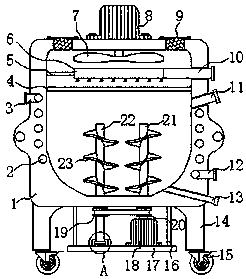
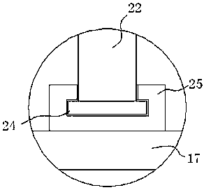
[0024] Embodiment one, with reference to figure 1 , image 3 and Figure 5 : An organic fertilizer drying device for biogas combustion and energy saving, comprising a drying box 1, a partition 4 is welded near the top of the drying box 1, and a herringbone vent hole 401 is evenly opened in the partition 4, which can prevent the organic fertilizer from moving to the partition 4 Above, the top center of the drying box 1 is fixed with a first drive motor 8 by bolts, the model of the first drive motor 8 is Y2-132M-4, and the output end of the first drive motor 8 is provided with a fan piece 7 through a shaft sleeve , and the fan piece 7 is located in the drying box 1, the bottom of the drying box 1 is welded with four vertical bars 16, and the end of the four vertical bars 16 away from the drying box 1 is welded with a support plate 17, and the top of the support plate 17 is fixed by bolts. The second drive motor 18, the model of the second drive motor 18 is Y2-90L-2, the output...
Embodiment 2
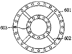
[0025] Embodiment two, refer to figure 2 : The designer arranges a drying assembly 6 between the partition plate 4 and the fan blade 7 in the drying box 1, the drying assembly 6 includes a plurality of ring pipes 601, and the bottoms of the plurality of ring pipes 601 are connected with an air outlet nozzle 603 , in order to realize the drying of the organic fertilizer in the drying box 1, the corresponding sides of the plurality of ring pipes 601 are communicated with connecting pipes 602, so that the communication of the plurality of ring pipes 601 can be realized through the connecting pipes 602, wherein one of the outer ring pipes The two sides of the pipe 601 are respectively welded with two fixed rods 5 and the air intake pipe 10, the other ends of the two fixed rods 5 are welded to the inner wall of the dry box 1, and the other end of the air intake pipe 10 extends to the outside of the dry box 1, multiple The vertical center line of the ring pipe 601 is located on the...
Embodiment 3
[0026] Embodiment three, refer to figure 1 and Figure 4 : The designer has a spiral groove 2 in the box wall of the drying box 1, and the two sides of the drying box 1 are respectively embedded with a water inlet pipe 3 and a water outlet pipe 12 near the bottom and the top, and one end of the water inlet pipe 3 and the water outlet pipe 12 are respectively Connected with both ends of the spiral groove 2, a T-shaped air outlet pipe 9 is embedded on the top of the drying box 1, and the T-shaped air outlet pipe 9 is fixed to the drying box 1 by bolts, and a mesh is welded inside the T-shaped air outlet pipe 9 Plate 26, the bottom of the drying box 1 is welded with a pillar 14 near the edge, and the bottom of the pillar 14 is fixed with a universal wheel 15 by bolts, so as to realize the movement of the drying box 1, and one side of the drying box 1 is located on the side of the dividing plate 4 A feed pipe 11 is connected to the bottom, and a discharge pipe 13 is connected to ...
PUM
 Abstract
Description
Claims
Application Information
 - R&D
- Intellectual Property
- Life Sciences
- Materials
- Tech Scout
- Unparalleled Data Quality
- Higher Quality Content
- 60% Fewer Hallucinations
Browse by: Latest US Patents, China's latest patents, Technical Efficacy Thesaurus, Application Domain, Technology Topic, Popular Technical Reports.
© 2025 PatSnap. All rights reserved.Legal|Privacy policy|Modern Slavery Act Transparency Statement|Sitemap|About US| Contact US: help@patsnap.com


