
Tire dismounting device with air leaking detecting function

A tire disassembly and equipment technology, applied in tire installation, tire parts, transportation and packaging, etc., can solve the problems of increasing the work intensity of the repairman, moving tires laboriously, and tedious operation process, so as to achieve rich equipment functions and manual operation space. Large, strong overall effect of equipment

Inactive Publication Date: 2019-09-27
三门星凯智能科技有限公司
View PDF7 Cites 8 Cited by
  • Summary
  • Abstract
  • Description
  • Claims
  • Application Information

AI Technical Summary

Problems solved by technology

[0002] As we all know, tires are usually made of wear-resistant rubber materials, and the service life of general tires is about three years. In addition, the service life of tires is also related to the distance traveled by the vehicle; tires may be punctured due to sharp objects on the road or other special conditions during use. In order to prevent traffic accidents, the tire pressure of the general car is checked at least once a month; generally, when the tire inspection is carried out in the auto repair shop, the repairer needs to manually inflate the tire to measure the tire pressure. The operation process is cumbersome, and manual measurement also has certain errors; In addition, one car needs to measure four tires. There are a large number of cars in the auto repair shop for maintenance and testing every day. The process of manually measuring the tire pressure will greatly increase the work intensity of the repairman. The tires are installed on the dismantling equipment. Some vehicles have huge tires, and it is very laborious to move the tires every time. Therefore, it is necessary to design a tire dismantling equipment with air leakage detection function to solve the above problems.

Method used


Image

  • Tire dismounting device with air leaking detecting function
  • Tire dismounting device with air leaking detecting function
  • Tire dismounting device with air leaking detecting function

Examples


Embodiment Construction

[0024] Combine below Figure 1-6 The present invention is described in detail, and for convenience of description, the orientations mentioned below are now stipulated as follows: figure 1 The up, down, left, right, front and back directions of the projection relationship itself are the same.

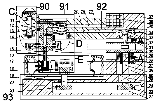
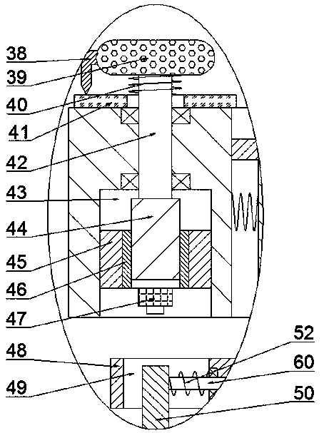
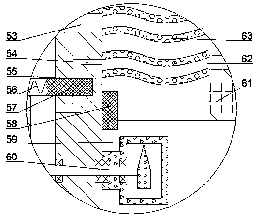
[0025] combined with Figure 1-6 The tire dismounting device with air leakage detection function includes a fuselage 37, the bottom wall of the fuselage 37 is provided with a first transmission chamber 22, and a rotary device for driving the tire to rotate is arranged in the first transmission chamber 22. Mechanism 93, the rotating mechanism 93 includes a mounting block 18, a wheel hub 17 can be fixedly installed on the mounting block 18, a tire 16 is installed on the wheel hub 17, and the left end of the wheel hub 17 is fixed with a The tire valve 67 inflated in the wheel hub 17 and the tire 16, the wheel hub 17 and the tire 16 form a tire;

[0026] The top wall of the first transmis...


PUM


Abstract

The invention provides a tire dismounting device with an air leaking detecting function. The device comprises a device body, wherein a first transmission chamber is formed in the bottom wall of the device body; a rotating mechanism for driving the tire to rotate is arranged in the first transmission chamber; the rotating mechanism comprises a mounting block, and a hub is fixedly mounted on the mounting block; and a tire is mounted on the hub. According to the device, the tire air leaking condition is regularly detected through air pressure, and meanwhile, the tire subjected to air leaking is automatically dismounted, thus the device is rich in functions; in addition, the device fits tires with various sizes; the manual operation space of a worker is large; the use is convenient and quick; the operation of manually independently measuring the air leaking of the tire in running is avoided; the device is high in automation degree, and both time and force are saved; the air pressure in the tire supports the dismounting of the tire; the dynamic energy utilization rate of the device is high; the whole dismounting process is flexible to respond; and the device is high in integrity.

Description

technical field [0001] The invention relates to the field of automobile maintenance and repair, in particular to a tire dismantling device with an air leakage detection function. Background technique [0002] As we all know, tires are usually made of wear-resistant rubber materials, and the service life of general tires is about three years. In addition, the service life of tires is also related to the distance traveled by the vehicle; tires may be punctured due to sharp objects on the road or other special conditions during use. In order to prevent traffic accidents, the tire pressure of the general car is checked at least once a month; generally, when the tire inspection is carried out in the auto repair shop, the repairer needs to manually inflate the tire to measure the tire pressure. The operation process is cumbersome, and manual measurement also has certain errors; In addition, one car needs to measure four tires. There are a large number of cars in the auto repair sh...

Claims


Application Information

Patent Timeline
Patent Type & Authority Applications(China)
IPC IPC(8): B60C25/05
CPCB60C25/0506
Inventor 王坚
Owner 三门星凯智能科技有限公司
Learn More